
Compressed air servicing unit

Inactive Publication Date: 2001-01-02
FESTO AG & CO KG
View PDF20 Cites 19 Cited by
  • Summary
  • Abstract
  • Description
  • Claims
  • Application Information

AI Technical Summary

Benefits of technology

In the case of the compressed air servicing unit of the invention it is possible for the individual modules to be placed initially in any desired, convenient sequential order and number. For the electrical together only the bus line of the bus system is employed, which excludes the possibility of incorrect connections, since all modules are connected together in the same fashion with one another. An adaptation of lines is not necessary either, since the bus line may be continued from one module to another, independently of the order of the modules. On connection of a further module the same is connected with the directly adjacent module. Direct connections with the monitoring module are not necessary in the bus system of the invention. For each extension of the system it is only necessary for a further piece of bus line to be added, all bus line pieces being identical. It is in this manner that a more rapid and absolutely reliable electrical connection is produced and between the modules, it being possible to maintain the bus line unchanged for a change in the order of the modules, merely a replugging being necessary. At the monitoring module only one bus line connection is required, independently of how many modules are connected. The number of modules may be increased as well without limitation, the connection of a new module, which was not previously provided, only involving a re-programming of the central unit if anything.
It is an advantage if the central unit and / or the bus subscriber stations are arranged in separate housings and the same are able to be plugged, or so connected in some other way, to the housings of the modules that a sequential arrangement is produced. This means that practically the entire bus system may be plugged prior to or after mechanical assembly and the individual bus subscriber stations may be readily replaced by others. A further advantage is that the modules may be supplied in extremely simple designs even without a bus system, if the separate housings are omitted.
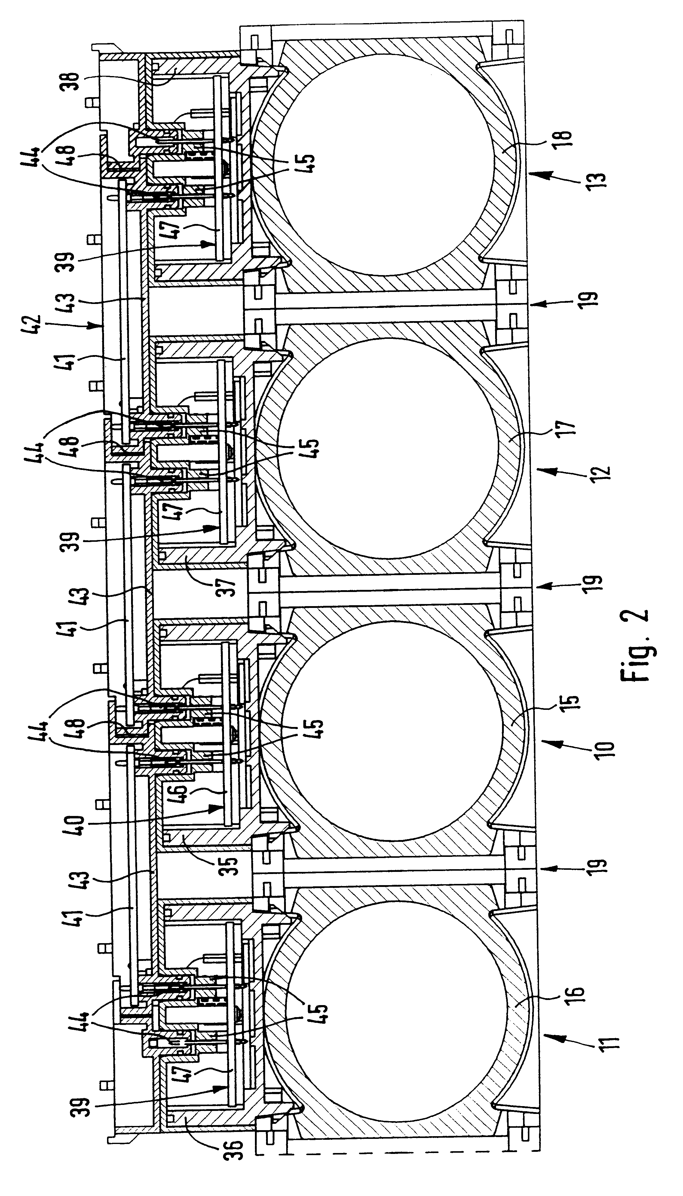
An advantageous design of the bus system is furthermore produced if the modules, including the monitoring module, are provided with electrical plug means for plug connection of the bus line, which accordingly connects together the bus subscriber stations of all modules and the central unit and is provided with corresponding mating plug means, the bus line being more particularly designed in the form of a bus line strand or bus line bar. It is preferred for the separate housings at least of the bus subscriber stations to be provided with such electrical plug means for plugging in the bus line. Accordingly it is also possible for the bus line to be fitted in place by plugging after mechanical assembly and for it to be partially or completely replaced at any time. Furthermore, in the case of a change in the mechanical order of the modules or in the case of expansion by the addition of further modules it is possible for the bus line to be returned to its functional state simply by replugging without any wrong connections being possible.
The separate housings are furthermore preferably provided with additional electrical plug means for the plug connections with actuators and / or sensors of the respective module. An even more flexible and simpler adaptation as regards changes in order and of expansion of the module arrangement is achieved, if the bus line in the form of a bus line bar consists of individual bar elements, of which each connects the plug means of two adjacent modules and each plug means is designed to receive two mating plug means of two sequentially arranged bar elements. If the modules possess the same width it is possible for all bar elements to be of identical design, expansion with a further module only involving the plugging in place of an additional bar element for expansion of the bus line. In this respect the bar elements are best toothingly engaged with each other in the plugged in position in order to achieve a mechanically and accordingly also electrically more stable arrangement.
It is furthermore an advantage if the components necessary for the respective module functions are at least partly provided with electrical mating plug means, which are connected with actuators and / or sensors of this respective component, the fitting in position of this component on a module housing meaning that the mating plug means automatically produces a plug connection with the additional plug means of the separate housing arranged on the module housing. Accordingly no separate working and assembly operations for the separate connection of the actuators and sensors with the component subscriber stations are required.

Problems solved by technology

The disadvantage of this arrangement is that more particularly in the case of a large number of sequentially arranged modules there is a disorderly cluster of wires which will be even larger if the monitoring module is to control actuators in the modules in addition.
Since each plug connection is associated with a given cable of one of the connected modules, any improper insertion of a plug will lead to improper function.
Lastly there is the further disadvantage that the maximum possible number of plug connections must be provided initially on the monitoring module, as otherwise expansion by the addition of further modules will not be possible.
Since however only a smaller number of modules is selected, such an elaborate arrangement of plug connections is unnecessarily expensive and extravagant in space.
Additional modules, which were not originally provided and for which no plug connection is present, may not be fitted, even in the case of a re-programming or modification of the circuit of the monitoring module.

Method used


Image

  • Compressed air servicing unit
  • Compressed air servicing unit
  • Compressed air servicing unit

Examples


Embodiment Construction

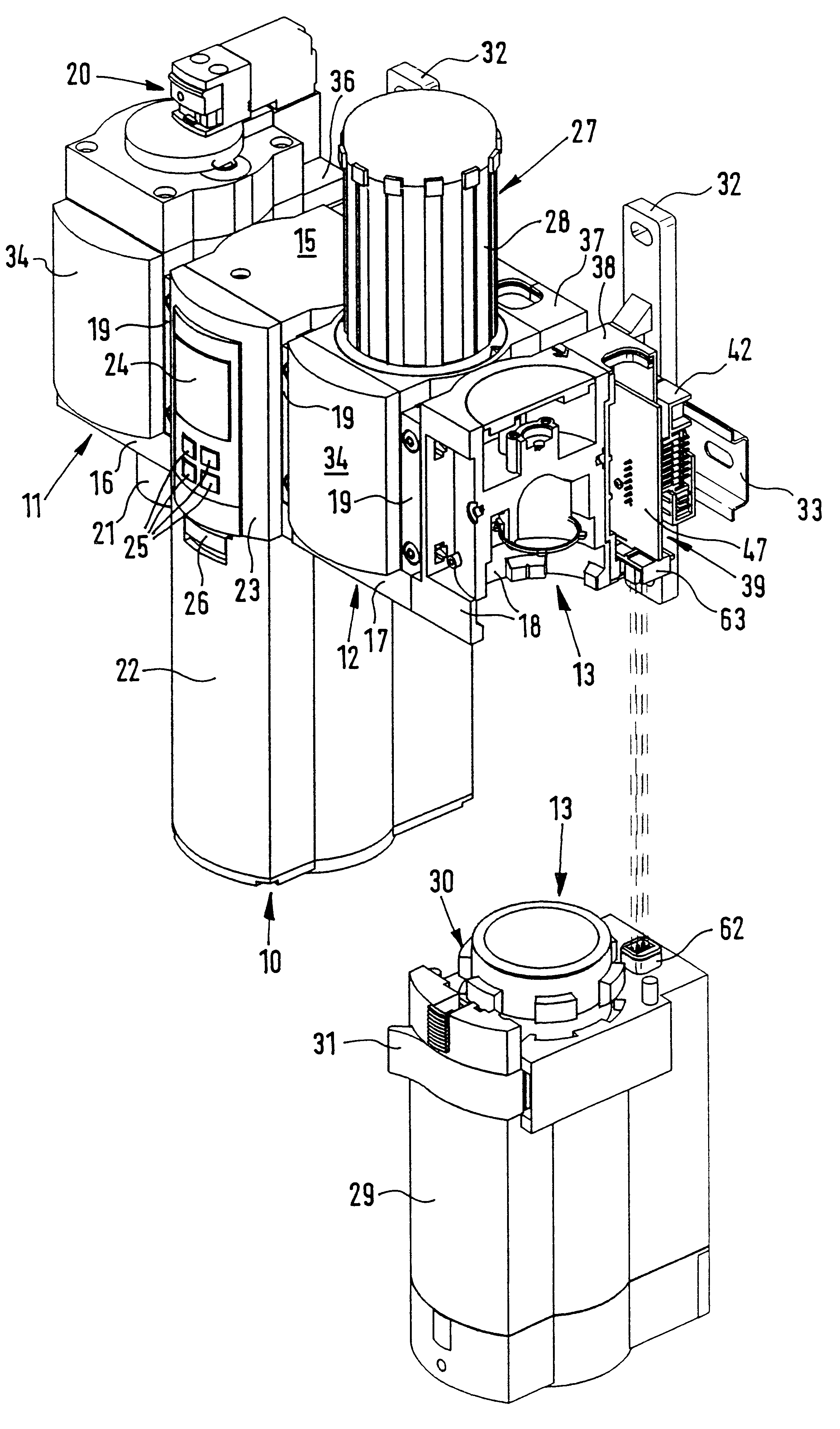
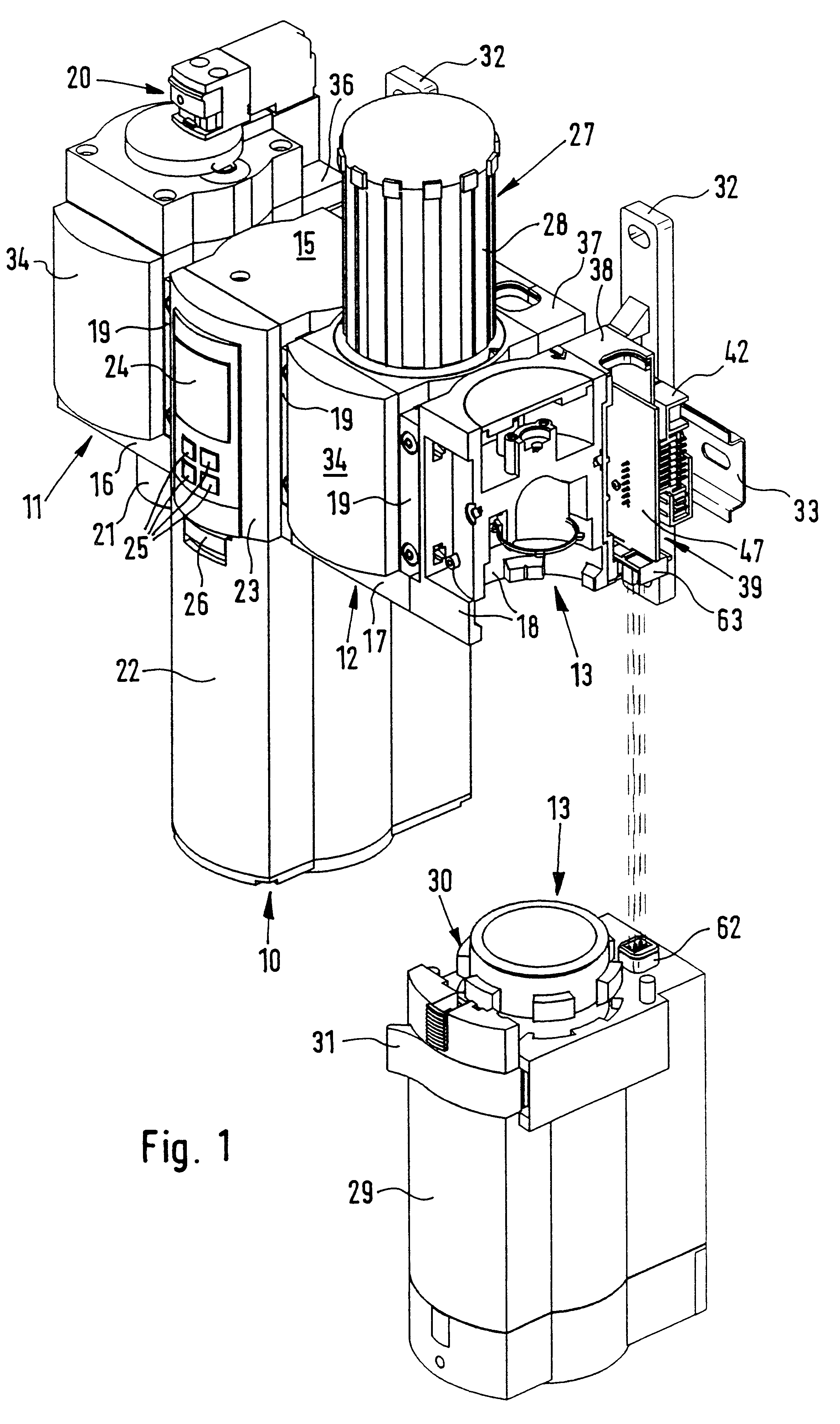
In the case of the embodiment of the invention, represented in FIGS. 1 and 2, in the form of a compressed air servicing unit a monitoring module 10 is connected with three further modules 11 through 13 in a sequential arrangement. The module 11 is designed in the form of a switching valve module and possesses a switching valve 20 in order to be able to permit the passage of compressed air supplied from the inlet or to shut off such air. The module 12 is designed as a pressure controlling module in order to be able to be set any desired pressure as required in particular circumstances. The partially sectioned module 13, which is cut into two parts, is designed in the form of a filter module.

The four modules 10 through 13 may also be connected together in a different sequential arrangement, further modules with known functions being fitted, such as a soft start module for controlled build up of pressure, an oiler module for controlled supply of oil or a flow rate measuring module for ...


PUM


Abstract

A compressed air servicing unit is provided, which possesses a plurality of modules, such as pressure controllers, filters oilers or the like, adapted to be attached together in any desired order and having module housings, one of such modules being designed in the form of a monitoring unit for the other modules and being electrically connected with same. A bus line, connecting the modules together, of a bus system is provided and furthermore the monitoring module performing control functions as well is provided with a central unit of the bus system and the other modules are provided respectively with a bus subscriber station, sensors and / or actuators present in or on a module respectively, being connected with the associated bus subscriber station. This means that the modules may be arranged in practically any desired order and in an desired number without any problem occurring with electrical wiring or due to incorrect bus subscriber station connections.

Description

The invention relates to a compressed air servicing unit, comprising a plurality of modules, such as pressure controllers, filters oilers or the like, adapted to be attached together in any desired order and having module housings, one of such modules being designed in the form of a monitoring unit for the other modules and being electrically connected with same.THE PRIOR ARTIn the case of a compressed air servicing unit of this type as disclosed in the patent publication WO 96 / 38 671 the monitoring unit possesses plug connections on its lower side for plugs of transmission lines, which lead to the other modules in order to supply sensor signals of such modules to the monitoring unit. The disadvantage of this arrangement is that more particularly in the case of a large number of sequentially arranged modules there is a disorderly cluster of wires which will be even larger if the monitoring module is to control actuators in the modules in addition. Since each plug connection is assoc...

Claims


Application Information

Patent Timeline
IPC IPC(8): F15B1/00F15B1/26F15B13/00F15B21/00F15B21/04F15B13/08F15B21/048
CPCF15B1/26F15B13/0825F15B13/0853F15B13/0857F15B13/086F15B13/0864F15B13/0867F15B13/0875F15B13/0892F15B13/0896F15B21/048
Inventor STOLL, KURTBERNER, MICHAEL
Owner FESTO AG & CO KG
Learn More