Cleaning apparatus using photocatalyst
a technology of cleaning apparatus and photocatalyst, which is applied in the field of cleaning apparatus, can solve the problems of plaque being a harmful substance, increasing the amount of cleaning substances, and increasing the speed of cleaning
- Summary
- Abstract
- Description
- Claims
- Application Information
AI Technical Summary
Benefits of technology
Problems solved by technology
Method used
Image

Examples
embodiment no.2
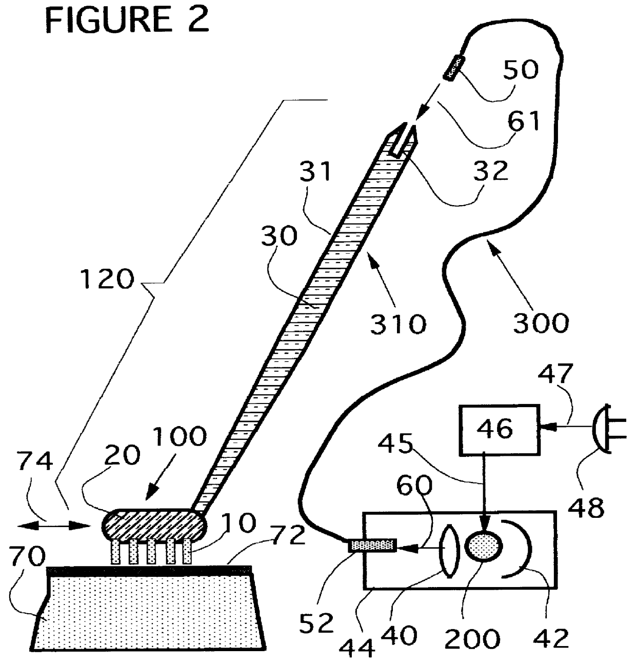
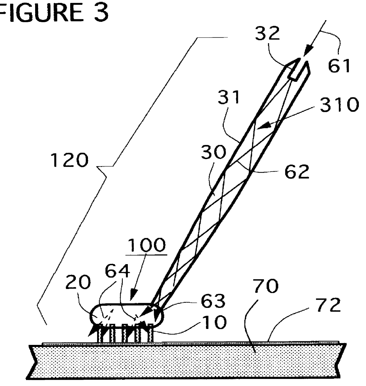
FIG. 6 shows second preferred embodiment of the present invention, in which a cleaning apparatus is roughly comprised of a cleaning tool 130, a light source 200, a light control circuit device 46 and an optical fiber 300.
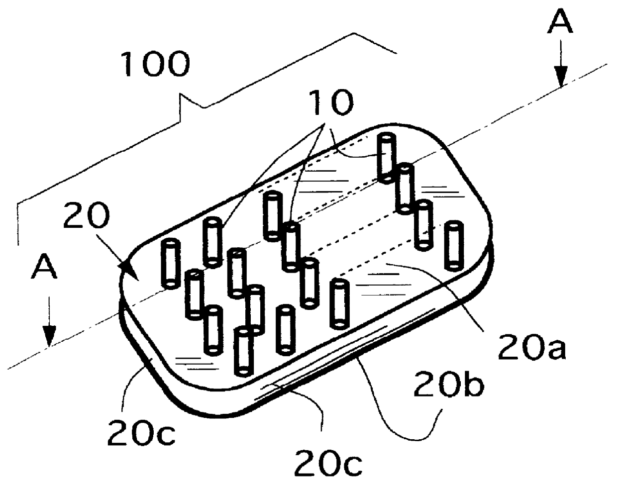
The cleaning tool 130 is further comprised of a cleaning head 100 and a handle 320. The handle 320 is formed as a pipe of hollow tube and it is extended from the cleaning head 100 or it is connected with the cleaning head 100. A cleaning head 100 is further comprised of a group of brushes with photocatalyst 10 (photocatalyst brushes) and a transparent brush supporter 20 by which the photocatalyst brushes 10 is fixed. Many light diffusing elements or particles 22 (shown in FIG. 4) may preferably be embedded in the transparent brush supporter 20.
In the embodiment NO.2, one terminal of the optical fiber 300 is connected to the cleaning head 100 by such as an optical fiber connector. The optical fiber 300 is passing inside through the handle of tube 320 and is going out...
embodiment no.3
FIG. 7 shows third preferred embodiment of the present invention, in which a cleaning apparatus is roughly comprised of a cleaning tool 140, a light source 200 and a light control circuit device 46.
The cleaning tool 140 is further comprised of a cleaning head 100, a transparent neck 100a of a part of the cleaning head 100 and a handle 330. The handle 330 is formed as a pipe of hollow tube and it is extended from the transparent neck 100a, which is enlarged as taper shape in cross-section toward the handle 330.
A cleaning head 100 is further comprised of a group of brushes with photocatalyst 10 (photocatalyst brushes) and a transparent brush supporter 20 by which the photocatalyst brushes 10 is fixed. Many light diffusing elements or particles 22 (shown in FIG. 4) may preferably be embedded in the transparent brush supporter 20.
In the embodiment NO.3, a cleaning tool 140, a light source 200, a light control circuit device 46 and a reflector42 are housed in a hollow portion of the hand...
embodiment no.4
FIG. 8 and FIG. 9 shows third preferred embodiment of the present invention. A cleaning apparatus is roughly comprised of a cleaning tool 150, a light source 200 and a light control circuit device 46, similar to the embodiment NO.3. The cleaning tool 150 is further comprised of a cleaning head 100, a transparent neck 100a of a part of the cleaning head 100 and a handle 330. The handle 330 is formed as a pipe of hollow tube in which the light source 200, the light control circuit device 46 and a ref lector are accommodated inside the hollow tube. UV light rays generating from the light source 200 are collected by a reflector 42 and are incident to the transparent neck 100a of taper shape. The light rays arrived at the he transparent neck 100a are transmitting directly to a transparent brush support 20 of the head 100 or transmitting by repeating multiple reflection 26 to the brush support 20. Incident light rays 63 into the brush supporter 20 are striking to much light diffusing part...
PUM
 Abstract
Description
Claims
Application Information
 - R&D
- Intellectual Property
- Life Sciences
- Materials
- Tech Scout
- Unparalleled Data Quality
- Higher Quality Content
- 60% Fewer Hallucinations
Browse by: Latest US Patents, China's latest patents, Technical Efficacy Thesaurus, Application Domain, Technology Topic, Popular Technical Reports.
© 2025 PatSnap. All rights reserved.Legal|Privacy policy|Modern Slavery Act Transparency Statement|Sitemap|About US| Contact US: help@patsnap.com