
Method for controlling energy storage system and devices performing method

Pending Publication Date: 2022-11-10
ELECTRONICS & TELECOMM RES INST
View PDF0 Cites 0 Cited by
  • Summary
  • Abstract
  • Description
  • Claims
  • Application Information

AI Technical Summary

Benefits of technology

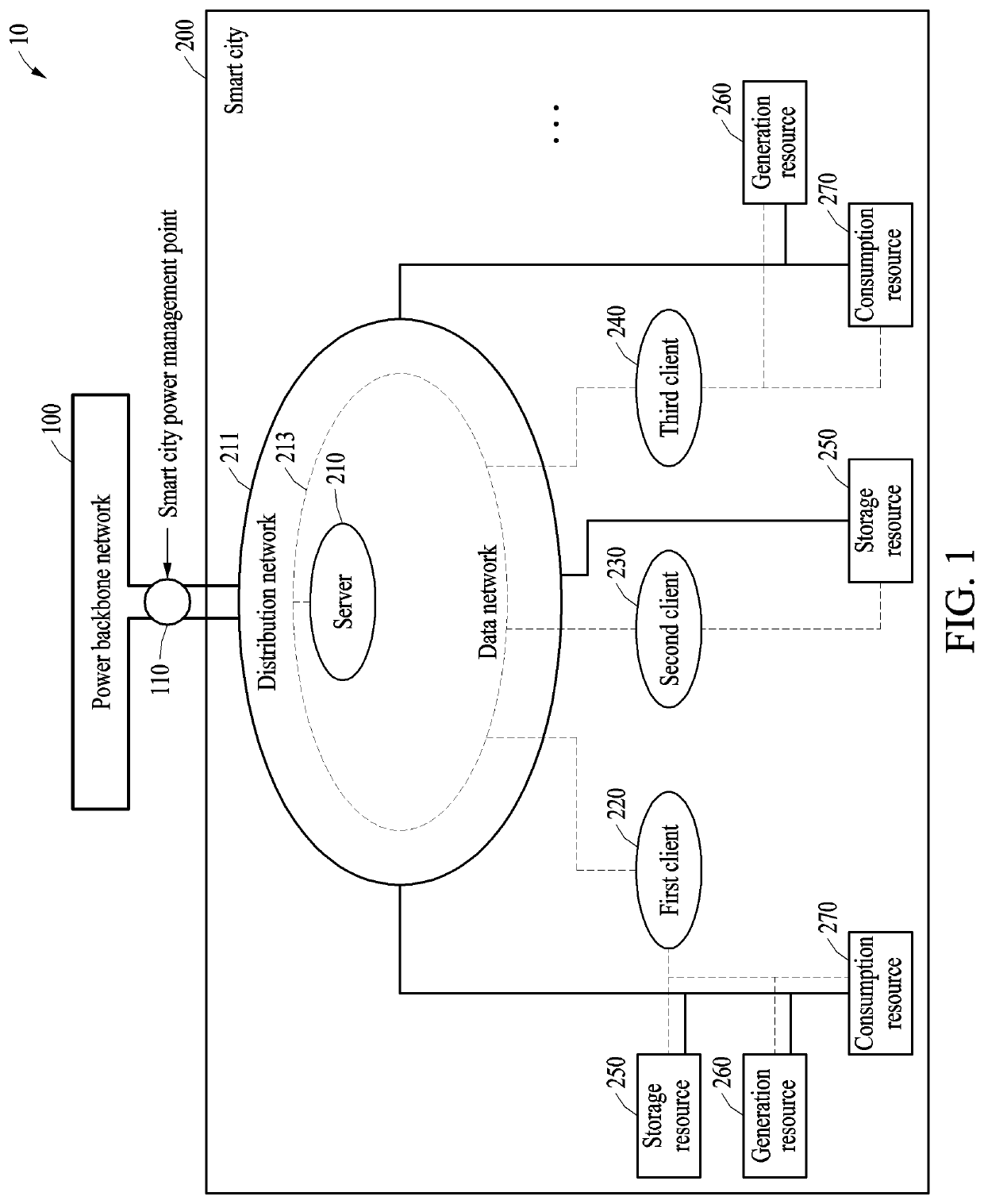
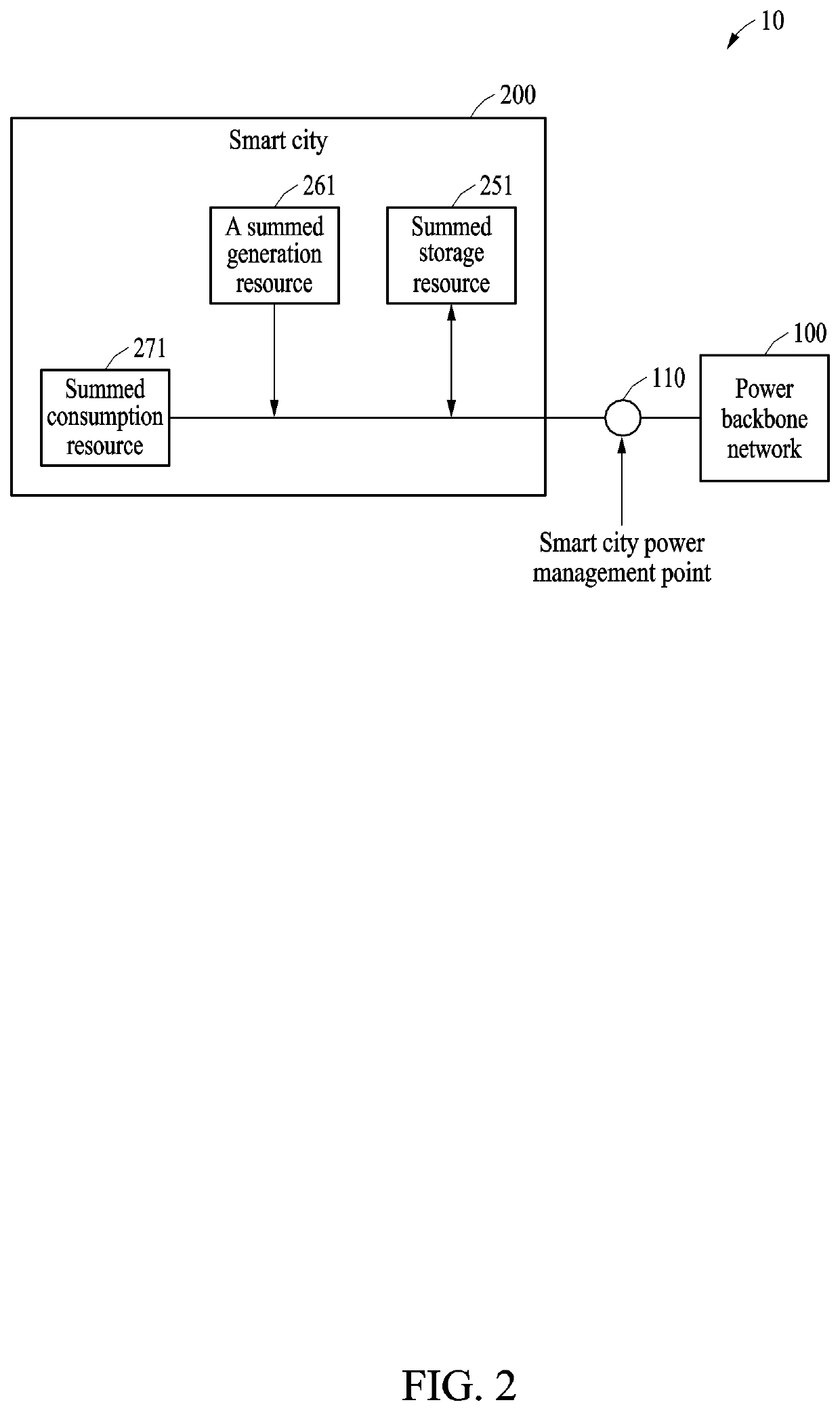
The patent text concerns an energy storage system (ESS) and its use in a complex environment, such as a smart city. The technical effect of the patent is to provide a method for efficiently managing a smart city as a whole, rather than individually managing each resource by applying a single-purpose technology. This involves defining the smart city as a single management unit and efficiently managing the relationship between the smart city and a power grid. The patent also includes a processor that corrects scheduling control information to prevent reverse transmission of power from the area to the power backbone network.

Problems solved by technology

There is a limitation in efficiently managing a complex environment in which various power energy consumption sources, supply resources, and storage resources are mixed, such as a smart city.
However, a technical issue is not limited to the above-described technical issues, and other technical issues may exist.
The method may include an operation of settling, based on the energy information to which the corrected scheduling control information is reflected, a cost of power generated in the area with the plurality of clients.
The processor may be configured to settle, based on the energy information to which the corrected scheduling control information is reflected, a cost of power generated in the area with the plurality of clients.

Method used


Image

  • Method for controlling energy storage system and devices performing method
  • Method for controlling energy storage system and devices performing method
  • Method for controlling energy storage system and devices performing method

Examples


Embodiment Construction

[0044]The following structural or functional descriptions of example embodiments described herein are merely intended for the purpose of describing the example embodiments described herein and may be implemented in various forms. Here, the example embodiments are not construed as limited to the disclosure and should be understood to include all changes, equivalents, and replacements in the idea and the technical scope of the disclosure.

[0045]Although terms of “first,”“second,” and the like are used to explain various components, the components are not limited to such terms. These terms are used only to distinguish one component from another component. For example, a first component may be referred to as a second component, or similarly, the second component may be referred to as the first component in the scope of the present disclosure.

[0046]When it is mentioned that one component is “connected” or “accessed” to another component, it may be understood that the one component is dire...


PUM


Abstract

A method for controlling an energy storage system (ESS) and devices performing the method are disclosed. A method for controlling an ESS according to example embodiments, the method includes an operation of analyzing energy information of an area for which a peak power load is to be calculated received from a plurality of clients included in the area, an operation of generating, based on an analysis result, scheduling control information for controlling the ESS connected to the plurality of clients on a daily basis, an operation of determining, based on the scheduling control information, whether to generate real-time control information for controlling the ESS on a basis of a predetermined control time period, and an operation of correcting, based on the real-time control information, the scheduling control information.

Description

CROSS-REFERENCE TO RELATED APPLICATIONS[0001]This application claims the benefit of Korean Patent Application No. 10-2021-0060141 filed on May 10, 2021, and Korean Patent Application No. 10-2022-0000248 filed on Jan. 3, 2022, in the Korean Intellectual Property Office, the entire disclosures of which are incorporated herein by reference for all purposes.BACKGROUND[0002]1. Field of the Invention[0003]One or more example embodiments relate to a method for controlling an energy storage system (ESS), and devices performing the method.[0004]2. Description of the Related Art[0005]An energy storage system (ESS) enables free charging and discharging of power, and accordingly a power grid may be efficiently managed using the ESS.[0006]The ESS can be used to reduce a maximum load of a unit customer or building in terms of demand management, and a cost of using power energy using a time-of-use rate plan, or can be used to stabilize an output of new and renewable energy by adjusting, a generati...

Claims


Application Information

Patent Timeline
IPC IPC(8): H02J13/00H02J3/38
CPCH02J13/00022H02J13/00002H02J3/381H02J2310/10H02J2310/60H02J3/32H02J2300/24H02J7/35H02J2310/12G06Q50/06H02J3/003H02J3/004G06Q30/0201G06Q10/063
Inventor SHIN, CHEOL-HO
Owner ELECTRONICS & TELECOMM RES INST
Learn More