Vehicle cleaner system and sensor system with vehicle cleaner
a technology of vehicle cleaner and sensor system, which is applied in the direction of vehicle cleaning, cleaning using liquids, instruments, etc., can solve the problems of in-vehicle camera lens, which is an imaging surface, and may become dirty, so as to reduce power consumption and achieve effective cleaning methods
- Summary
- Abstract
- Description
- Claims
- Application Information
AI Technical Summary
Benefits of technology
Problems solved by technology
Method used
Image
Examples
first embodiment
[0081
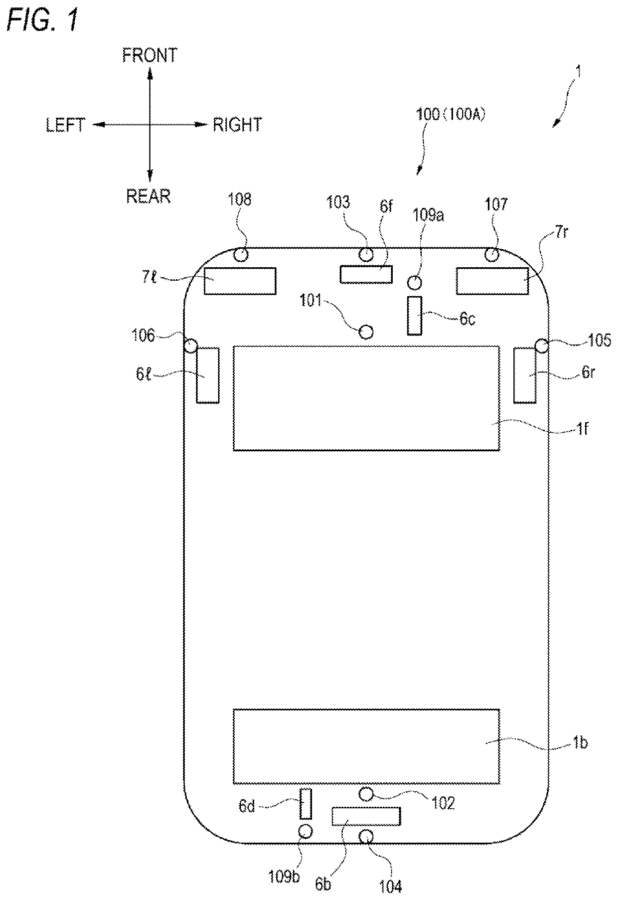
[0082]FIG. 1 is a top view showing a vehicle 1 equipped with a vehicular cleaner system 100 (hereinafter, referred to as a cleaner system 100) according to a first embodiment. The vehicle 1 includes the cleaner system 100. In the present embodiment, the vehicle 1 can travel in self-driving mode.
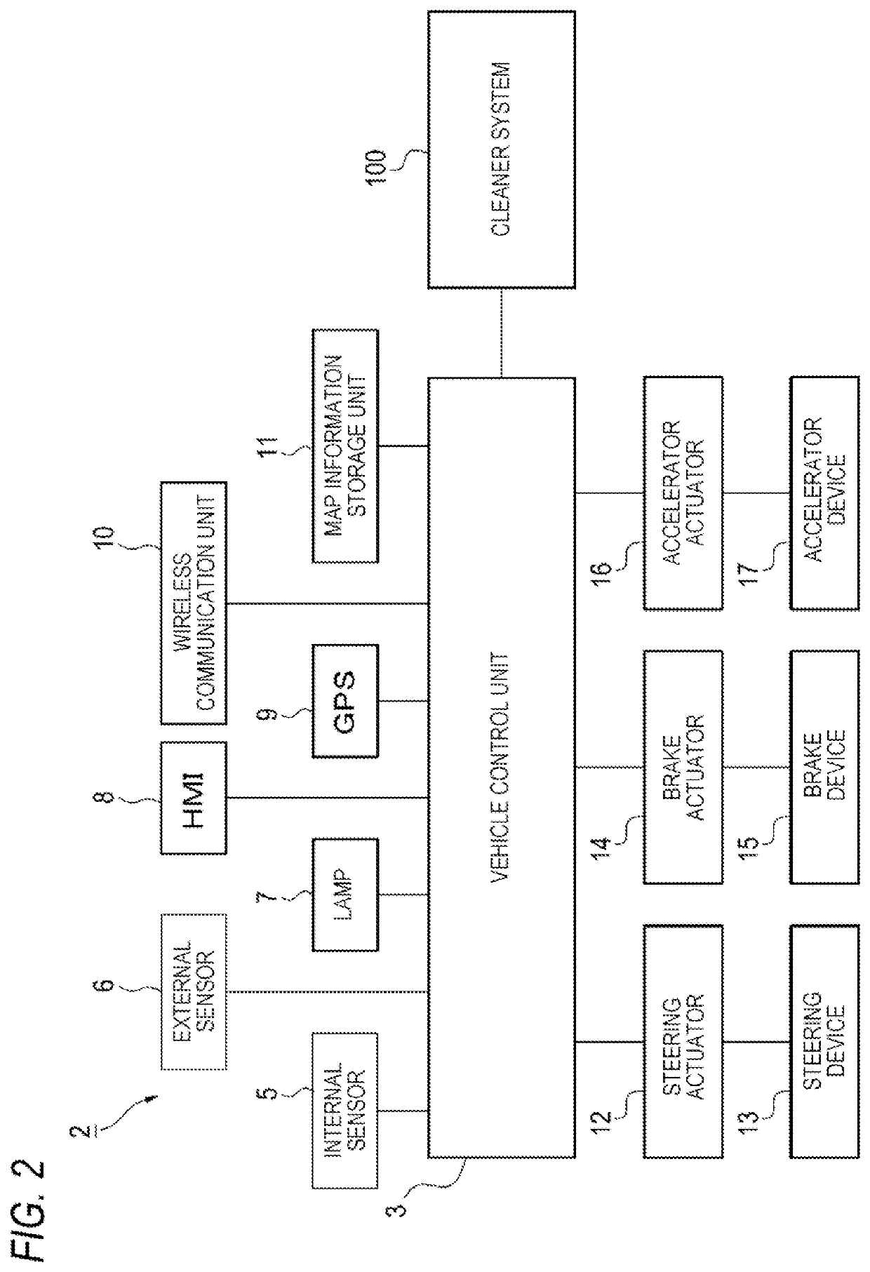
[0083]First, a vehicle system 2 of the vehicle 1 will be described with reference to FIG. 2. FIG. 2 is a block diagram showing the vehicle system 2. As shown in FIG. 2, the vehicle system 2 includes: a vehicle control unit 3; an internal sensor 5; an external sensor 6; a lamp 7; a human machine interface (HMI) 8; a global positioning system (GPS) 9; a wireless communication unit 10; and a map information storage unit 11. The vehicle system 2 further includes: a steering actuator 12; a steering device 13; a brake actuator 14; a brake device 15: an accelerator actuator 16; and an accelerator device 17.
[0084]The vehicle control unit 3 is configured with am electronic control unit (ECU). The...
second embodiment
[0182
[0183]As shown in FIG. 1, the vehicle 1 may include a sensor system 100A equipped with a vehicular cleaner (hereinafter, referred to as a sensor system 100A) according to a second embodiment. The vehicle 1 can travel in self-driving mode in the second embodiment.
[0184]First, a vehicle system 202 according to the second embodiment of the vehicle 1. will be described with reference to FIG. 11. FIG. 11 is a block diagram showing the vehicle system 202. As shown in FIG. 11, the vehicle system 202 includes: the vehicle control unit 3; the internal sensor 5; the external sensor 6; the lamp 7: the human machine interface (HMO 8; the global positioning system (GPS) 9, the wireless communication unit 10; and the map information storage unit 11. The vehicle system 202 further includes: the steering actuator 12; the steering device 13, the brake actuator 14; the brake device 15, the accelerator actuator 16; and the accelerator device 17. Since these components are similar to those in the ...
third embodiment
[0215
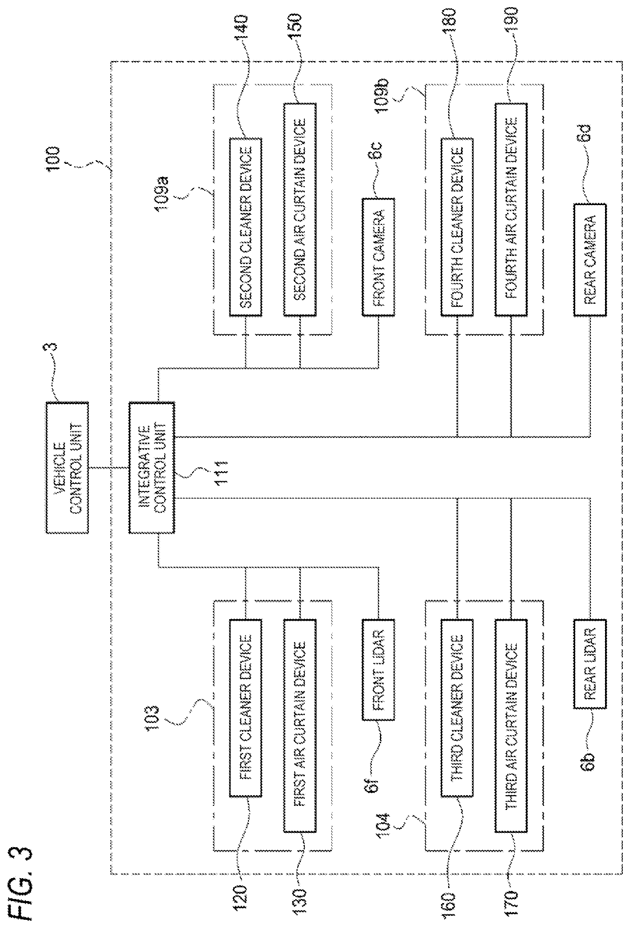
[0216]FIG. 14 is a block diagram showing a sensor system 100B according to a third embodiment.
[0217]As shown in FIG. 14, the normal dirt determination unit 221 may be included in the vehicle control unit 3. In the present embodiment, the vehicle control unit 3 determines operation of the cleaner unit 110 based on the output of the external sensor 6. An integrative control unit 320 operates a specific cleaner unit 110 based on a signal front the vehicle control unit 3 for operating the specific cleaner unit 110. That is, the vehicle control unit 3 may be configured to determine the dirt on the external sensor 6 when the external sensor 6 is set to the normal mode. In this case, the in control unit 320 of the sensor system 10013 includes; the fixed dirt determination unit 222: the sensor restoration determination unit 223; the first mode-switching unit 224; the second mode-switching unit 225; and the cleaner operation unit 226.
[0218]Since the flowchart showing processing executed...
PUM
 Abstract
Description
Claims
Application Information
 - R&D
- Intellectual Property
- Life Sciences
- Materials
- Tech Scout
- Unparalleled Data Quality
- Higher Quality Content
- 60% Fewer Hallucinations
Browse by: Latest US Patents, China's latest patents, Technical Efficacy Thesaurus, Application Domain, Technology Topic, Popular Technical Reports.
© 2025 PatSnap. All rights reserved.Legal|Privacy policy|Modern Slavery Act Transparency Statement|Sitemap|About US| Contact US: help@patsnap.com


