Electronic device including battery

Pending Publication Date: 2022-09-22
SAMSUNG ELECTRONICS CO LTD
View PDF0 Cites 0 Cited by
  • Summary
  • Abstract
  • Description
  • Claims
  • Application Information

AI Technical Summary

Benefits of technology

This patent provides a way to fix a battery in a slim electronic device, which increases the rigidity of the device and allows for better protection of the battery. This can be achieved by using a rigid substrate that replaces a support between the battery and the front or back cover of the device. By doing this, the device becomes more durable and can handle more battery capacity. Additionally, assembly convenience is improved because wireless charging and antenna components can be placed on the substrate. The overall thickness of the device is reduced, and the bending and torsional rigidity of the device is secured through the substrate and its fixing bracket.

Problems solved by technology

In the case of stacking the battery and parts (e.g., an FPCB on which at least one antenna is located) in the thickness direction in the electronic device to meet the demands for slimness of the electronic device, there may be a limitation in reducing the thickness of the electronic device.

Method used


Image

  • Electronic device including battery
  • Electronic device including battery
  • Electronic device including battery

Examples


Embodiment Construction

[0027]Hereinafter, various example embodiments of the disclosure may be described with reference to accompanying drawings. Those of ordinary skill in the art will recognize that modifications, equivalents, and / or alternatives on the various example embodiments described herein can be variously made without departing from the scope and spirit of the disclosure.

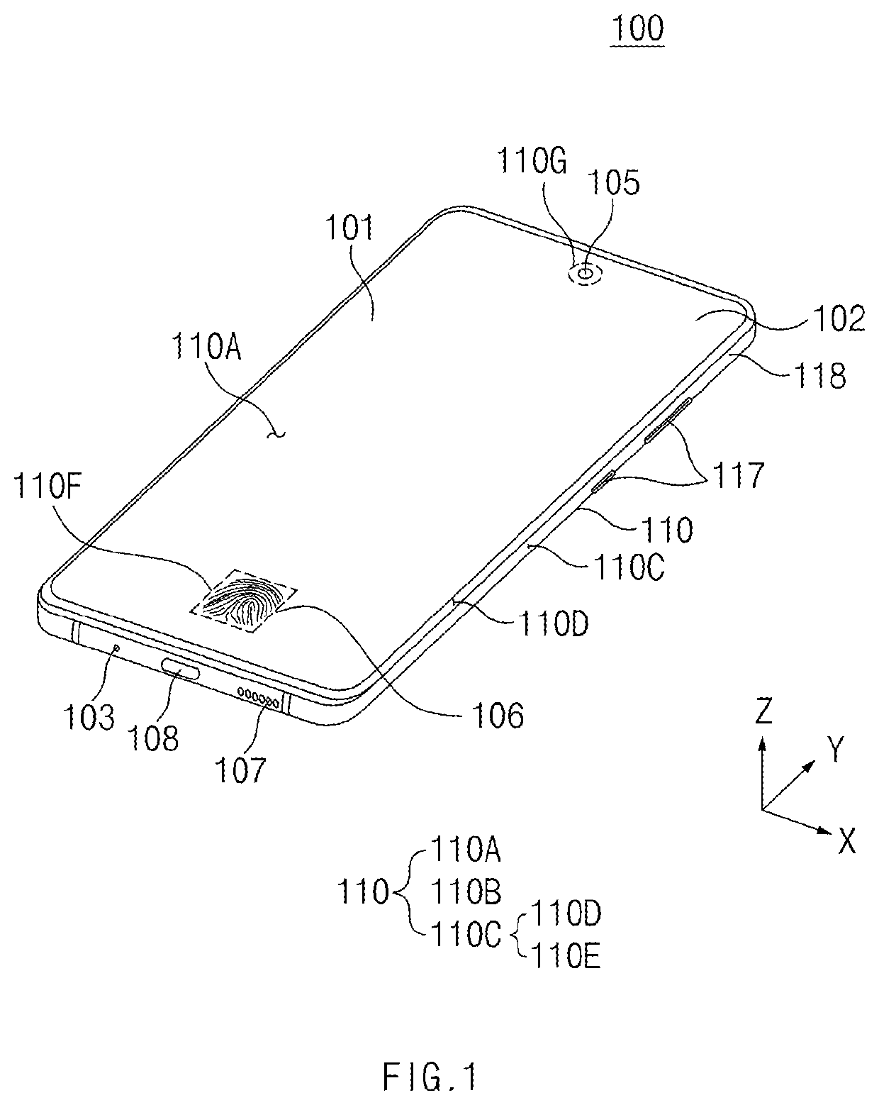
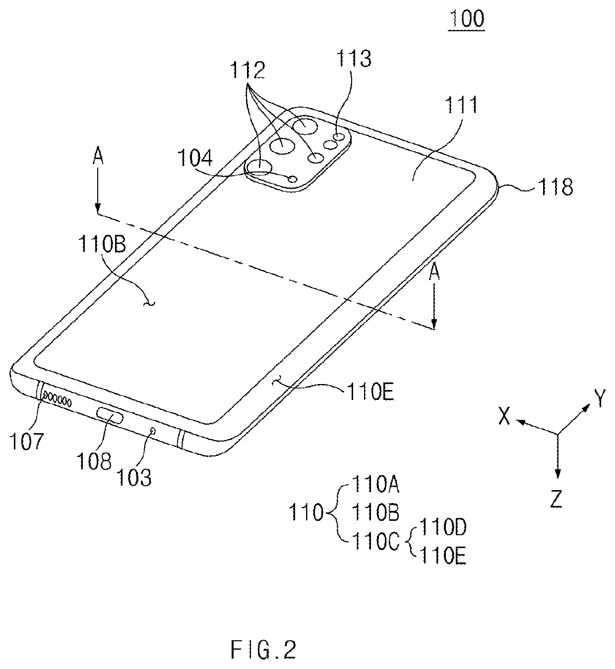
[0028]FIG. 1 is a front perspective view of an electronic device according to various embodiments. FIG. 2 is a rear perspective view of the electronic device according to various embodiments.

[0029]Referring to FIGS. 1 and 2, the electronic device 100 may include a housing 110 that includes a first surface (or, a front surface) 110A, a second surface (or, a rear surface) 110B, and a side surface 110C surrounding a space between the first surface 110A and the second surface 110B.

[0030]In another embodiment (not illustrated), the housing 110 may refer to a structure that forms some of the first surface 110A, the second surface 110...


PUM


Abstract

An electronic device according to an embodiment includes: a front plate forming a front surface of the electronic device, a back plate forming a rear surface of the electronic device, a support located between the front plate and the back plate and including a first surface facing the front plate and a second surface facing the back plate, the support having an opening formed through the first surface and the second surface, a display at least partially disposed on the first surface of the support, a first circuit board, at least a portion of which is disposed on the second surface of the support, the first circuit board including a rigid area that at least partially covers the opening, and a battery disposed in the opening of the support and having a size smaller than or substantially the same as a size of the opening when the first surface or the second surface of the support member is viewed from above, and the battery is at least partially attached to the rigid area.

Description

CROSS-REFERENCE TO RELATED APPLICATIONS[0001]This application is a continuation of International Application No. PCT / KR2022 / 002912 designating the United States, filed on Mar. 2, 2022, in the Korean Intellectual Property Receiving Office and claiming priority to Korean Patent Application No. 10-2021-0036231, filed on Mar. 19, 2021, in the Korean Intellectual Property Office, the disclosures of which are incorporated by reference herein in their entireties.BACKGROUNDField[0002]The disclosure relates to an electronic device including a battery.Description of Related Art[0003]An electronic device may include a support member that supports structures such as a battery and a circuit board. The battery may be attached to one surface of the support member through an adhesive tape. A wireless charging coil, an MST antenna, an NFC antenna, and FPCBs for an interface may be disposed between the battery and a cover of a housing of the electronic device.[0004]In the case of stacking the battery...

Claims


Application Information

Patent Timeline
IPC IPC(8): H02J50/10H02J50/00H05K1/02H05K1/14
CPCH02J50/10H02J50/005H05K1/028H05K1/14H05K1/0203H05K2201/10128H05K2201/10037H05K2201/10098H05K1/147H05K3/4691H05K1/189H04M1/0262H04M1/0277
Inventor LEE, SEUNGHOONMOON, HEECHEULSON, KWONHOLEE, YONGSEOK
Owner SAMSUNG ELECTRONICS CO LTD
Why Eureka
Try Eureka