Apparatus for damping vibration

Active Publication Date: 2018-07-05
KOREA ADVANCED INST OF SCI & TECH
View PDF1 Cites 0 Cited by
  • Summary
  • Abstract
  • Description
  • Claims
  • Application Information

AI Technical Summary

Benefits of technology

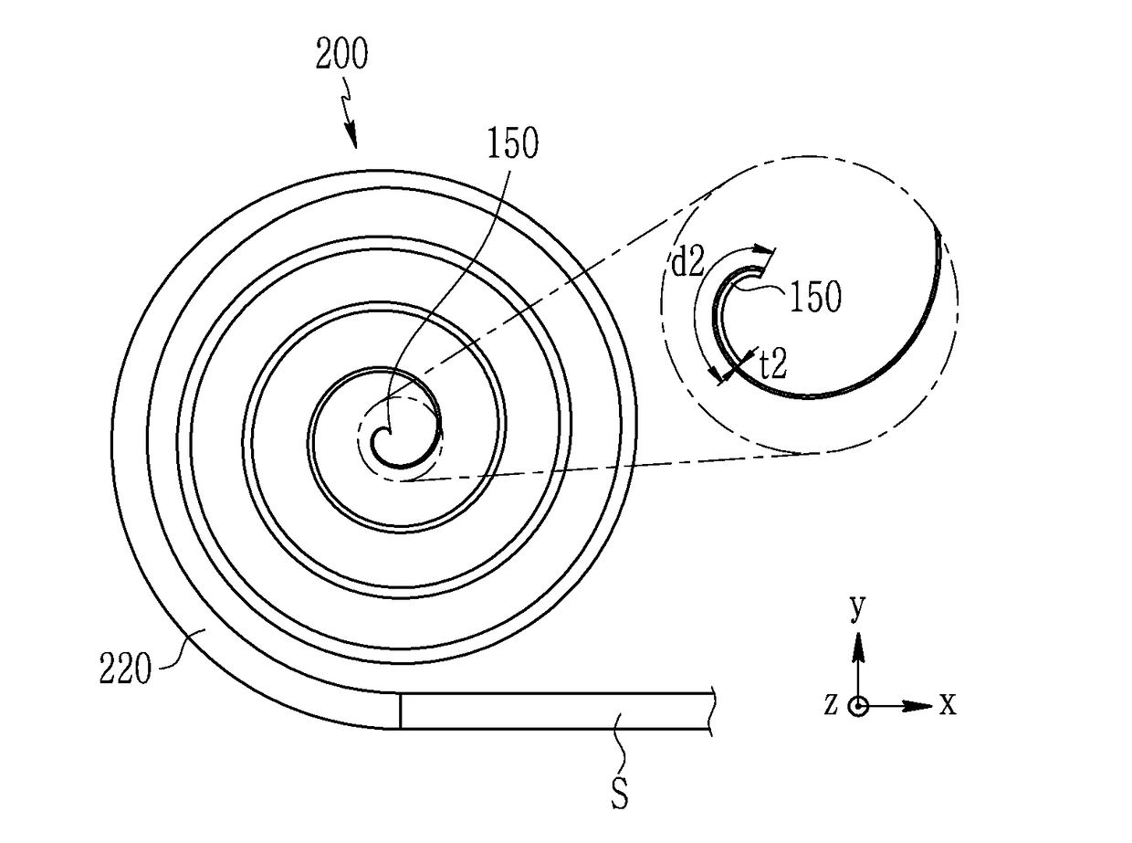
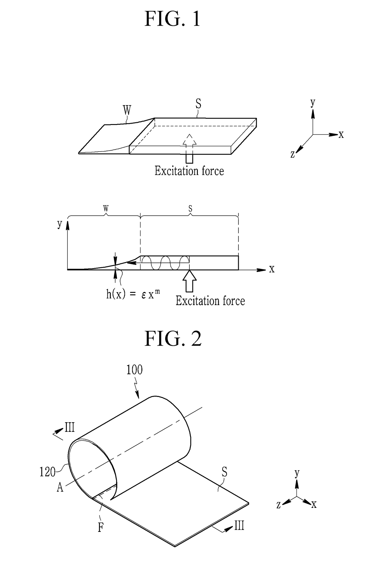
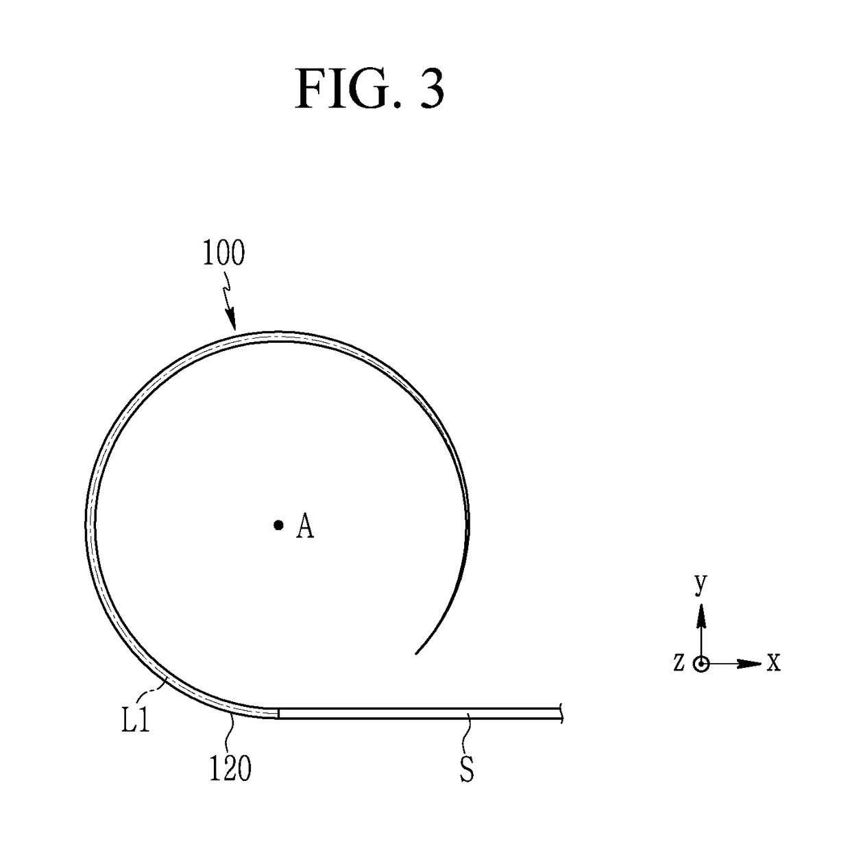
The patent describes a device that can effectively dampen vibrations and noise in a small space. This is achieved by bending the main body of the structure in a spiral manner while decreasing its thickness. This design allows for better vibration and noise damping in a compact space.

Problems solved by technology

However, a conventional method for damping the vibration by attaching the damping material to the surface of the structure may be an inefficient vibration damping method depending on a shape or size of the structure.

Method used


Image

  • Apparatus for damping vibration
  • Apparatus for damping vibration
  • Apparatus for damping vibration

Examples


Embodiment Construction

[0038]Hereinafter, the present invention will be described more fully with reference to the accompanying drawings, in which exemplary embodiments of the invention are shown. As those skilled in the art would realize, the described embodiments may be modified in various different ways, all without departing from the spirit or scope of the present invention.

[0039]The drawings and description are to be regarded as illustrative in nature and not restrictive. Like reference numerals designate like elements throughout the specification.

[0040]In addition, the size and thickness of each configuration shown in the drawings are arbitrarily shown for better understanding and ease of description, but the present invention is not limited thereto.

[0041]Throughout the present specification, when any one part is referred to as being “connected to” another part, it means that the one part and the other part are “directly connected to” each other or are “indirectly connected to” each other with anoth...


PUM


Abstract

A vibration damping apparatus according to an exemplary embodiment of the present invention includes a main body extended from one side of a vibrating structure with a predetermined length from one end that contacts the structure to the other end, wherein at least a part of the main body is bent with a gradually decreasing thickness.

Description

CROSS-REFERENCE TO RELATED APPLICATION[0001]This application claims priority to and the benefit of Korean Patent Application No. 10-2016-0184277 filed in the Korean Intellectual Property Office on Dec. 30, 2016, the entire contents of which are incorporated herein by reference.BACKGROUND OF THE INVENTION(a) Field of the Invention[0002]The present invention relates to a vibration damping apparatus. More particularly, the present invention relates to an apparatus that is provided in one side of a structure to dampen vibration generated from the structure.(b) Description of the Related Art[0003]Effective damping of vibration in a thin plate or beam structure is a major consideration in design and analysis of various machine systems. In many industry fields, a surface of the plane or beam structure is treated with a thin damping material to dampen vibration. However, a conventional method for damping the vibration by attaching the damping material to the surface of the structure may be ...

Claims


Application Information

Patent Timeline
IPC IPC(8): F16F1/04F16F15/08
CPCF16F1/043F16F15/08F16F1/041F16F1/025F16F7/104F16F15/04
Inventor JEON, WONJU
Owner KOREA ADVANCED INST OF SCI & TECH
Why Eureka
Try Eureka