Dual coax network with power distribution and mid-span tap for signals and/or power from same

a coax network and coaxial cable technology, applied in the field of communication networks, can solve the problems of reducing the distance that a signal can travel through the coax cable, affecting the performance of the coax network, so as to achieve less attenuation, less interference, and greater power level

Pending Publication Date: 2022-09-22
COMMSCOPE TECH LLC
View PDF0 Cites 0 Cited by
  • Summary
  • Abstract
  • Description
  • Claims
  • Application Information

AI Technical Summary

Benefits of technology

The patent text describes a solution for improving the performance of a communication system by expanding the frequency bands of the forward and reverse paths. However, this solution also has its limitations due to the attenuation of signals in coaxial cables at higher frequencies. The dual coaxial communication system allows for higher power levels to be carried over the two coaxial cables, which can be used for powering auxiliary units or amplifiers along the cable's length. The tap, which is a conductive metallic outer housing, can be made with a dielectric inner layer to make it less susceptible to corrosion and water intrusion. The technical effects of the patent text include improved signal performance, higher power levels, and reduced interference with other communication networks.

Problems solved by technology

However, increasing the frequency bands to include frequencies above 1 GHz, e.g., 1.8 GHz, diminishes signal performance, as attenuation increases significantly in a coaxial cable at higher frequencies, which reduces the distance that a signal can travel through the coaxial cable.
Also, higher frequencies can interfere with other communication networks in the area, e.g., LTE networks.
The diplexers complicate the design of amplifiers 21 and require tuning, which can be labor intensive.

Method used


Image

  • Dual coax network with power distribution and mid-span tap for signals and/or power from same
  • Dual coax network with power distribution and mid-span tap for signals and/or power from same
  • Dual coax network with power distribution and mid-span tap for signals and/or power from same

Examples


Embodiment Construction

[0029]The present invention now is described more fully hereinafter with reference to the accompanying drawings, in which embodiments of the invention are shown. This invention may, however, be embodied in many different forms and should not be construed as limited to the embodiments set forth herein; rather, these embodiments are provided so that this disclosure will be thorough and complete, and will fully convey the scope of the invention to those skilled in the art.

[0030]Like numbers refer to like elements throughout. In the figures, the thickness of certain lines, layers, components, elements or features may be exaggerated for clarity. Broken lines illustrate optional features or operations unless specified otherwise.

[0031]The terminology used herein is for the purpose of describing particular embodiments only and is not intended to be limiting of the invention. Unless otherwise defined, all terms (including technical and scientific terms) used herein have the same meaning as c...


PUM


Abstract

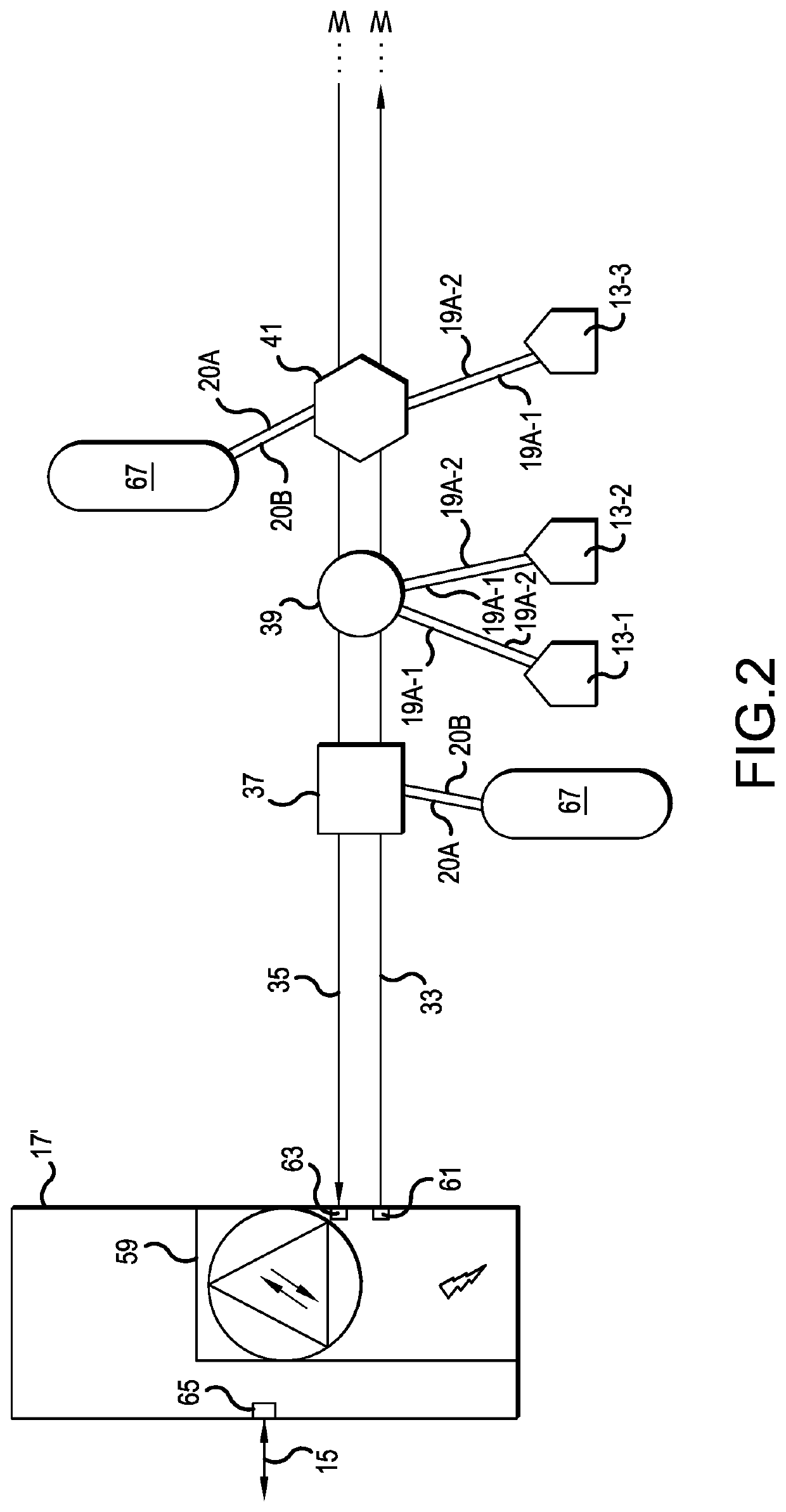
A communication network includes first and second coaxial cables. The first cable transmits forward path, downstream signals to customer devices. The second cable receives reverse path, upstream signals from customer devices. In a preferred embodiment, the downstream bandwidth exceeds 500 MHz and the upstream bandwidth exceeds 500 MHz, such as frequencies of 5 to 550 MHz in both the downstream and upstream directions. A power inserter provides a ground to first and second shielding layers of the first and second cables, a first part of a differential power signal to a center conductor of the first cable and a second part of the differential power signal to a center conductor of the second cable. A tap is also provided for the dual coaxial system, so as to provide access to the signals and / or power of the first and second cables without terminating the first and second cables.

Description

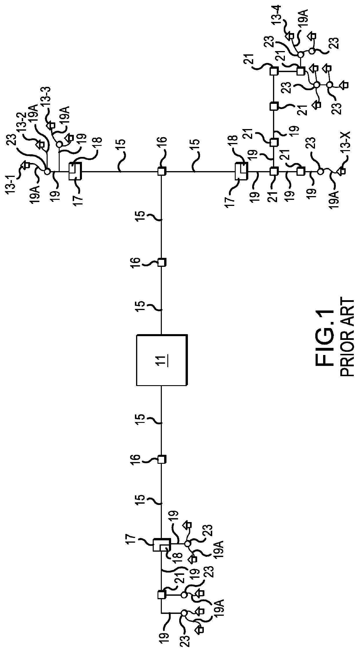
[0001]This application is a continuation of International Application No. PCT / US2020 / 062531, filed Nov. 29, 2020, which claims the benefit of U.S. Provisional Application No. 62 / 947,450, filed Dec. 12, 2019, both of which are herein incorporated by reference.BACKGROUND OF THE INVENTION1. Field of the Invention[0002]The present invention relates to a communication network employing first and second coaxial cables to provide downstream and upstream communications between a service provider and customer devices and to provide power over the coaxial cables for auxiliary units, like 5G small cell sites. The present invention also relates to a tap unit for accessing conductors of the coaxial cables mid-span, without terminating the coaxial cables.2. Description of the Related Art[0003]As shown in FIG. 1, communications networks often transmit cable television (CATV) signals and / or other information, like broadband Internet and / or telephone services, between a service provider center 11 an...

Claims


Application Information

Patent Timeline
IPC IPC(8): H01B11/06H01R9/05
CPCH01B11/06H01R9/0509H04B3/54H04B3/56H04B3/548
Inventor GEMME, CHRISTOPHER P.
Owner COMMSCOPE TECH LLC
Why Eureka
Try Eureka