
Holographic optical system

a technology of optical system and holographic lens, which is applied in the field of holographic optical system, can solve the problems of chromatic dispersion, affecting the angular position of the reticle, and becoming more difficult to correct the aberration inherent in off-axis design,

Pending Publication Date: 2022-08-04
TRULIFE OPTICS LTD
View PDF0 Cites 2 Cited by
  • Summary
  • Abstract
  • Description
  • Claims
  • Application Information

AI Technical Summary

Benefits of technology

This patent describes an optical system and a method for manufacturing a holographic optical element for use in a holographic reticle device. The system uses an extra holographic optical element to correct for geometrical aberrations caused by an off-axis reflective collimating system. This results in a well collimated beam with inefficient off the shelf elements. The system is designed to produce a virtual image at a far distance with low parallax error and can be produced cost-effectively with a compact design and low power draw. The holographic optical element is designed to compensate for chromatic dispersion and is immune to reticle parallax drift, which allows for the use of a cheap, low power LED as a replay source and reduces the need for electronics to control the wavelength of the laser. The system allows for a wide view of the real world with low stray light and a large aperture.

Problems solved by technology

The former is typically limited to red dots due to the aberrations inherent in off-axis designs becoming more challenging to correct for with extended sources (that is, the reticle is no longer a point source).
A known problem with holographic gunsights is chromatic dispersion, whereby the angular position of the reticle may change as the wavelength of the replay source changes.
However, this may cause chromatic blur, whereby the reticle image is blurred.
One option to mitigate this problem is to stabilise the laser wavelength, but this requires expensive and bulky electronics and / or lasers.
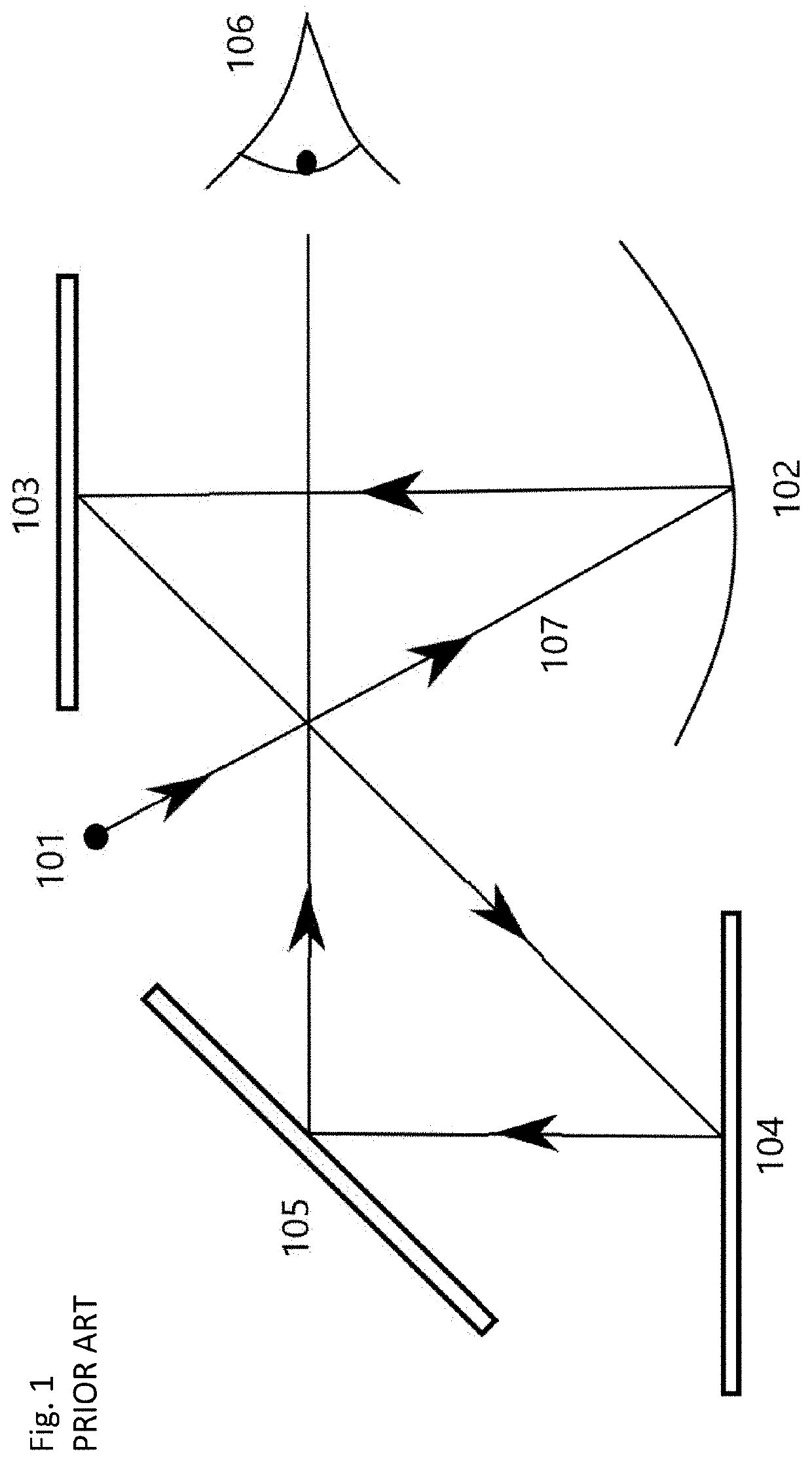
However, a parabolic mirror is expensive to make compared to a spherical mirror.
In contrast, a typical off-axis spherical mirror will have inherent spherical aberrations and, when it is used in an off-axis geometry, it will also produce coma aberrations.
It therefore cannot be used in place of a parabolic mirror without multiple corrective elements that only partially correct for dispersion, such that some parallax error remains.
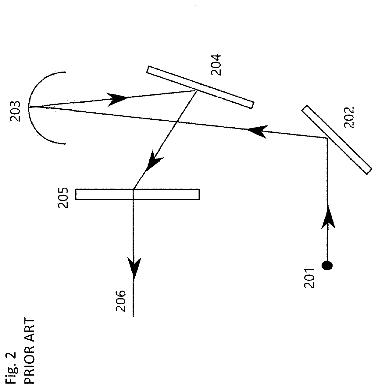
The spherical Mangin mirror 203 is an expensive element and still produces coma aberrations in an off-axis geometry.
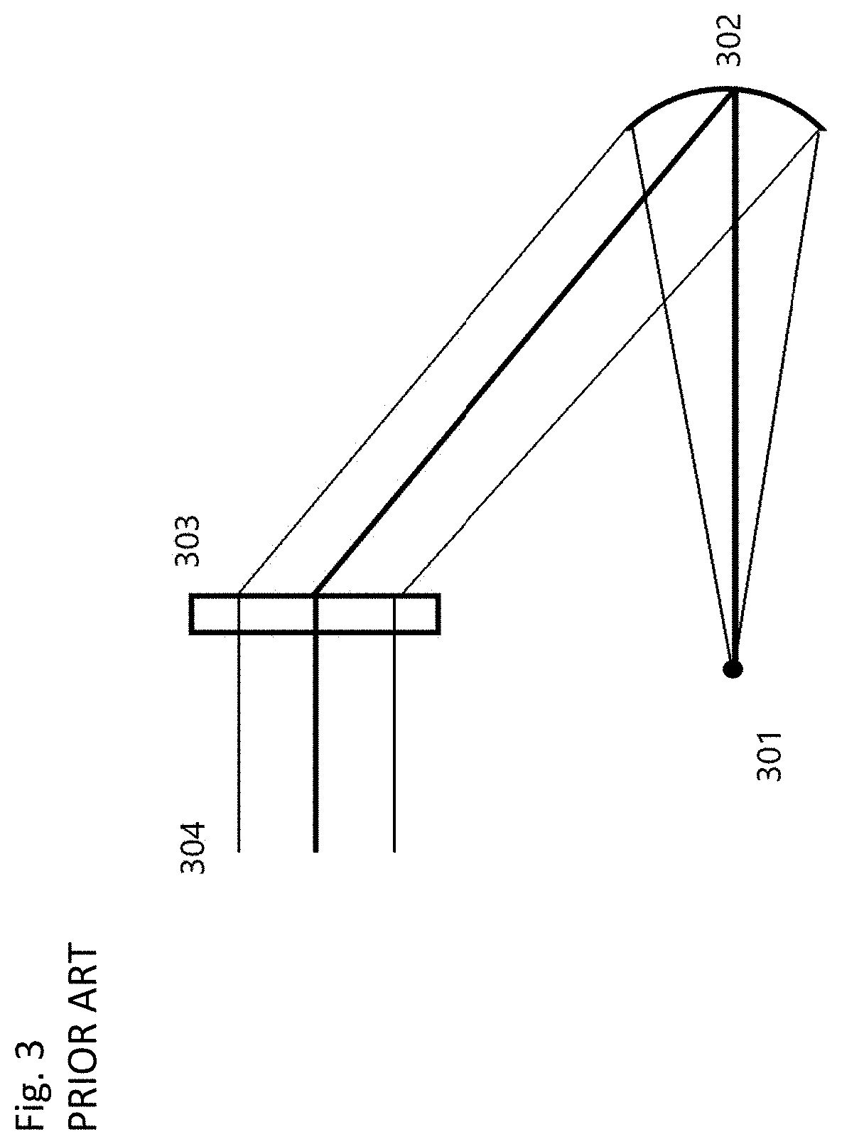
The diffraction grating on a physically curved surface 302 acts as a collimating element, but this is expensive to make.
Existing holographic gunsights therefore use expensive and / or bulky components to mitigate aberrations and chromatic dispersion.
This fills a gap in the market for such a device.
This may cause reticle drift, which is often mitigated by applying constant current and modulating the laser on and off rapidly or using a separate brightness control system (for instance, an adjustable polariser), which adds to cost and complexity.

Method used


Image

  • Holographic optical system
  • Holographic optical system
  • Holographic optical system

Examples


first embodiment

[0032]Referring first to FIG. 4, there is depicted a schematic diagram of an optical system for providing a red dot virtual image to a user in accordance with the disclosure. This is a nominal design, which has also been modelled in ray tracing software (as discussed with reference to FIG. 6 below) and fabricated experimentally. This comprises: a light source 401; a spherical mirror 403; a first holographic optical element (HOE) 404; a second HOE 405; and a beamsplitter 406. Reticle light is provided to a user eye 407. An axis of light 408 entering the user eye 407, comprising the reticle light and light passing through the beamsplitter 406 from outside the optical system is shown (such that the axis 408 is in line with the eye 407 of the user).

[0033]Light source 401 is a point source of light, for instance, a laser diode, VCSEL (Vertical Cavity Surface Emitting Laser) or a LED with a masking pinhole (not shown, typically of diameter approximately 50 μm). Emitted light chief (or cen...

second embodiment

[0073]Reference is now made to FIG. 5, in which there is depicted a schematic diagram of an optical system for providing a red dot virtual image to a user in accordance with the disclosure. This comprises: a light source 501; a spherical mirror 502; a waveguide 504; a holographic optical element (HOE) 503; and a diffraction grating 505. Reticle light is provided to a user eye 506. An axis of light 508 entering the user eye 506, comprising the reticle light and light passing through the waveguide 504 and the diffraction grating 505 from outside the optical system is shown.

[0074]Most of the elements of FIG. 4 are the same in FIG. 5, except the two diffraction gratings (of the HOE 503 and diffraction grating 505, respectively) are coupled via the waveguide 504 (a planar glass and / or plastic substrate, which may also be termed a lightguide) rather than via free space. The light source 501 is a point source with an emitted chief ray 507 incident on the spherical mirror 502. As in FIG. 4,...


PUM

PropertyMeasurementUnit
physical sizeaaaaaaaaaa
diameteraaaaaaaaaa
focal lengthaaaaaaaaaa

Abstract

A holographic optical system is provided, including: a light source; a collimator, arranged to receive from the light source and having an output surface configured to provide collimated light, optical properties of the collimator generating aberrations in the collimated light; and an aberration-compensating holographic optical element having a planar diffractive surface arranged to receive collimated light from the output surface, the planar diffractive surface having optical properties such that output light from the planar diffractive surface is compensated for the aberrations generated by the collimator.

Description

CROSS REFERENCE TO RELATED APPLICATION[0001]This application claims the benefit under 35 U.S.C. § 119(a) of United Kingdom Application No. GB2101488.1 filed Feb. 3, 2021, the contents of which are incorporated by reference herein in their entirety.BACKGROUND OF THE DISCLOSURE1. Field of the Disclosure[0002]The disclosure concerns a holographic optical system that may form part of a gunsight.2. Description of the Related Art[0003]Gunsights may be designed to provide a virtual image of a reticle overlaid on the real world, at a far focal plane (close to infinity). The reticle should have low parallax error (that is, the position of the reticle does not shift relative to the real world at a set focal plane). The reticle should be viewable over a relatively large eyebox, such that the physical size (aperture) of the reticle should be in the order of 25.4 mm (1 inch) to allow for easy viewing of the reticle. A reticle can be provided as either a dot (a magnified point source) or an exten...

Claims


Application Information

Patent Timeline
Patent Type & Authority Applications(United States)
IPC IPC(8): G03H1/04G02B5/32
CPCG03H1/0402G03H2222/12G03H2001/0439G02B5/32G02B23/105G02B27/34F41G1/30G03H2223/16G03H1/0465G03H2001/0473G03H2223/17G03H2222/53G03H1/0005G02B27/0037G02B27/0056G02B27/4211G02B27/4216
Inventor VOLKOV, ANDRIISHERLIKER, BEN
Owner TRULIFE OPTICS LTD
Learn More