
Illuminating apparatus and illuminance collection system

Pending Publication Date: 2022-08-04
TOYOTA JIDOSHA KK
View PDF2 Cites 0 Cited by
  • Summary
  • Abstract
  • Description
  • Claims
  • Application Information

AI Technical Summary

Benefits of technology

The patent describes a system for managing data from illuminating apparatuses to create a sunshine map. By collecting and connecting boundary points from multiple illuminating apparatuses, the system can generate a boundary line for an area with no data. This allows for accurate sunshine mapping even without data at intermediate locations. Additionally, the system can adapt to temporary fluctuations in illuminance and adjust the amount and details of data transmitted to the management apparatus. This means that the management system can effectively generate a sunshine map even when situations change. Overall, the system improves accuracy and efficiency in sunshine mapping.

Problems solved by technology

However, when the sunshine percentage is calculated based on weather information, solar orbit information, and three-dimensional map information as described in JP 2017-181089 A, the amount of calculation is enormous.
In addition, a divergence may occur between information on buildings recorded in a map and information on real buildings depending on the frequency of update of the three-dimensional map information, which leads to deterioration of the accuracy of calculating a sunshine percentage.
However, with this configuration, to generate a sunshine map with some degree of accuracy, each vehicle is required to transmit the data of illuminance at relatively high frequency, which leads to a significant increase in communication traffic.
An area in which a crossover phenomenon frequently occurs is regarded an area inappropriate for photovoltaic power generation.

Method used


Image

  • Illuminating apparatus and illuminance collection system
  • Illuminating apparatus and illuminance collection system
  • Illuminating apparatus and illuminance collection system

Examples


Embodiment Construction

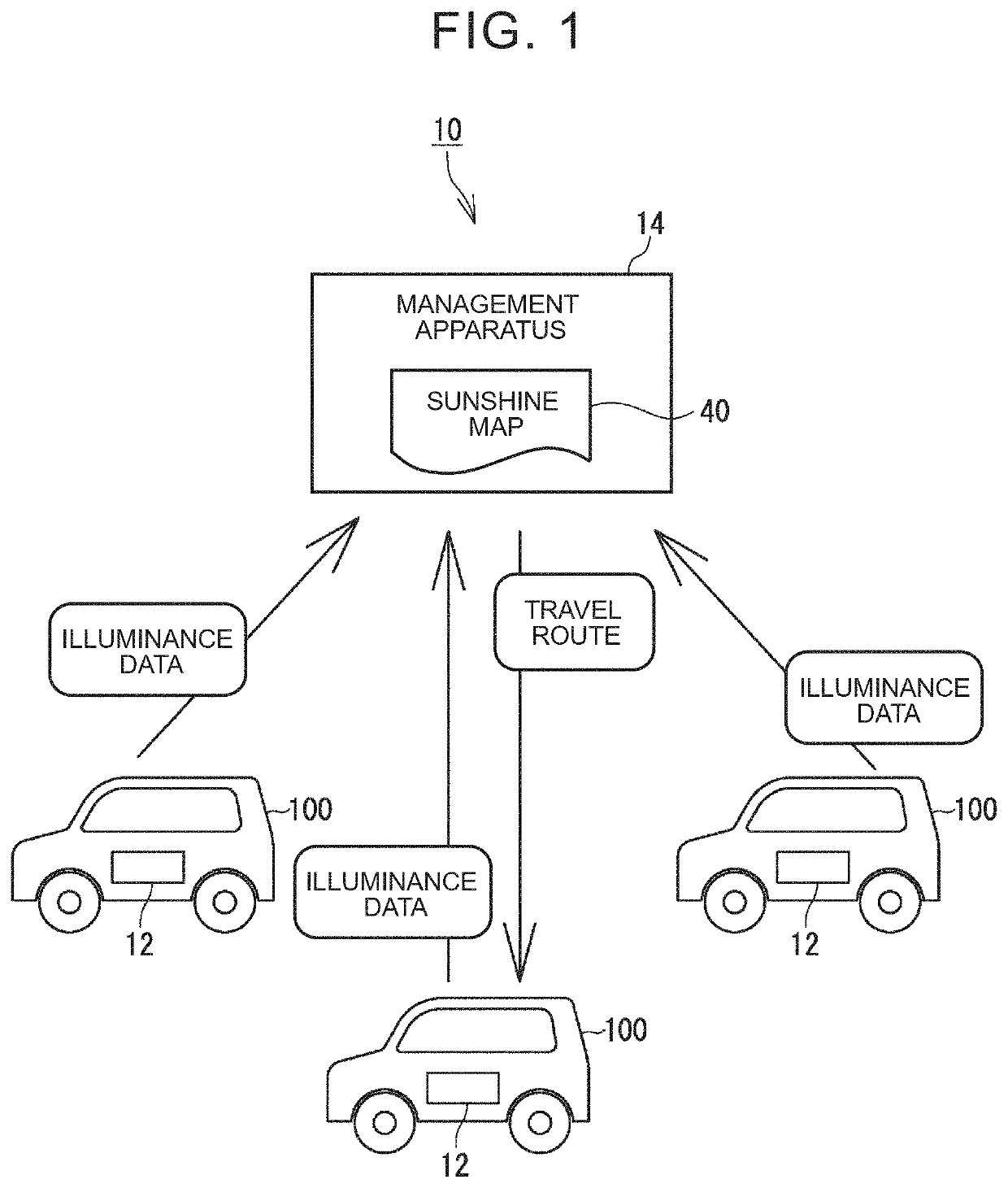
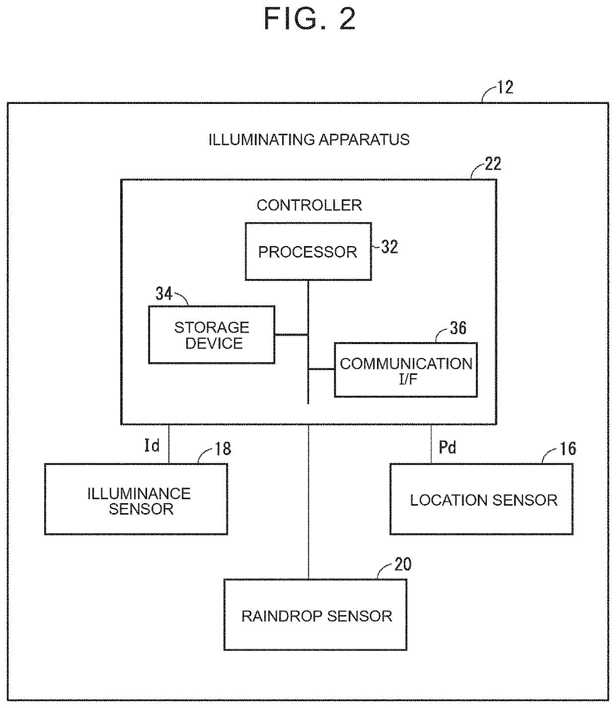
[0042]Hereinafter, the configuration of an illuminance collection system 10 will be described with reference to the accompanying drawings. FIG. 1 is a conceptual view showing the configuration of the illuminance collection system 10. FIG. 2 is a block diagram showing the configuration of an illuminating apparatus 12.

[0043]The illuminance collection system 10 collects illuminances in various places and includes a management apparatus 14 and a plurality of the illuminating apparatuses 12. The management apparatus 14 receives data of illuminance (hereinafter, referred to as illuminance data) from the illuminating apparatuses 12 and manages the illuminance data. The management apparatus 14 generates a sunshine map 40 based on the collected illuminance data. The sunshine map 40 shows the distribution of illuminance. The sunshine map 40 may be used to, for example, provide information on places suitable for photovoltaic power generation to vehicles or portable electronic devices (for exam...


PUM


Abstract

An illuminating apparatus includes an illuminance sensor mounted on a vehicle and configured to detect an illuminance outside the vehicle as a detected illuminance, a location sensor mounted on the vehicle and configured to detect a location of the vehicle as a detected location, and a controller configured to store one or more illuminance thresholds that are thresholds of the illuminance and monitor whether there is a crossover phenomenon that the detected illuminance crosses one of the one or more illuminance thresholds. The controller is configured to transmit crossing data, including information indicating the detected location when the crossover phenomenon occurs and information indicating the detected illuminance when the crossover phenomenon occurs, to a management apparatus outside the vehicle.

Description

CROSS-REFERENCE TO RELATED APPLICATION[0001]This application claims priority to Japanese Patent Application No. 2021-014622 filed on Feb. 1, 2021, incorporated herein by reference in its entirety.BACKGROUND1. Technical Field[0002]The specification describes an illuminating apparatus that provides a management apparatus with an illuminance according to a vehicle location, and an illuminance collection system that includes a plurality of illuminating apparatuses and a management apparatus.2. Description of Related Art[0003]In recent years, mounting a solar cell capable of generating electric power by using sunlight on a vehicle or a portable electronic device, such as a cellular phone, has been suggested. Such a vehicle or a portable electronic device is able to efficiently obtain electric power by passing through a place where the illuminance is high. Hitherto, a technique for generating a sunshine map showing the distribution of illuminance and providing information on a place suita...

Claims


Application Information

Patent Timeline
IPC IPC(8): G01C21/00B60W40/02G01J1/42G01C3/08
CPCG01C21/3807G01C21/3848B60W40/02B60W2420/40G01C3/08G01J2001/4266B60W2555/20G01J1/42G01W1/12G01C21/3469
Inventor AKISHINO, RYOTASAITO, HIROKI
Owner TOYOTA JIDOSHA KK
Learn More