
Fiber/wired communication system

a communication system and fiber-wire technology, applied in the field of communication systems, can solve problems such as stress on current systems to their limits, and achieve the effects of reducing the communication traffic between the concentrator and the head-end, increasing efficiency, and increasing reliability

Inactive Publication Date: 2010-06-08
AMERICAN TELEPHONE & TELEGRAPH CO
View PDF30 Cites 5 Cited by
  • Summary
  • Abstract
  • Description
  • Claims
  • Application Information

AI Technical Summary

Benefits of technology

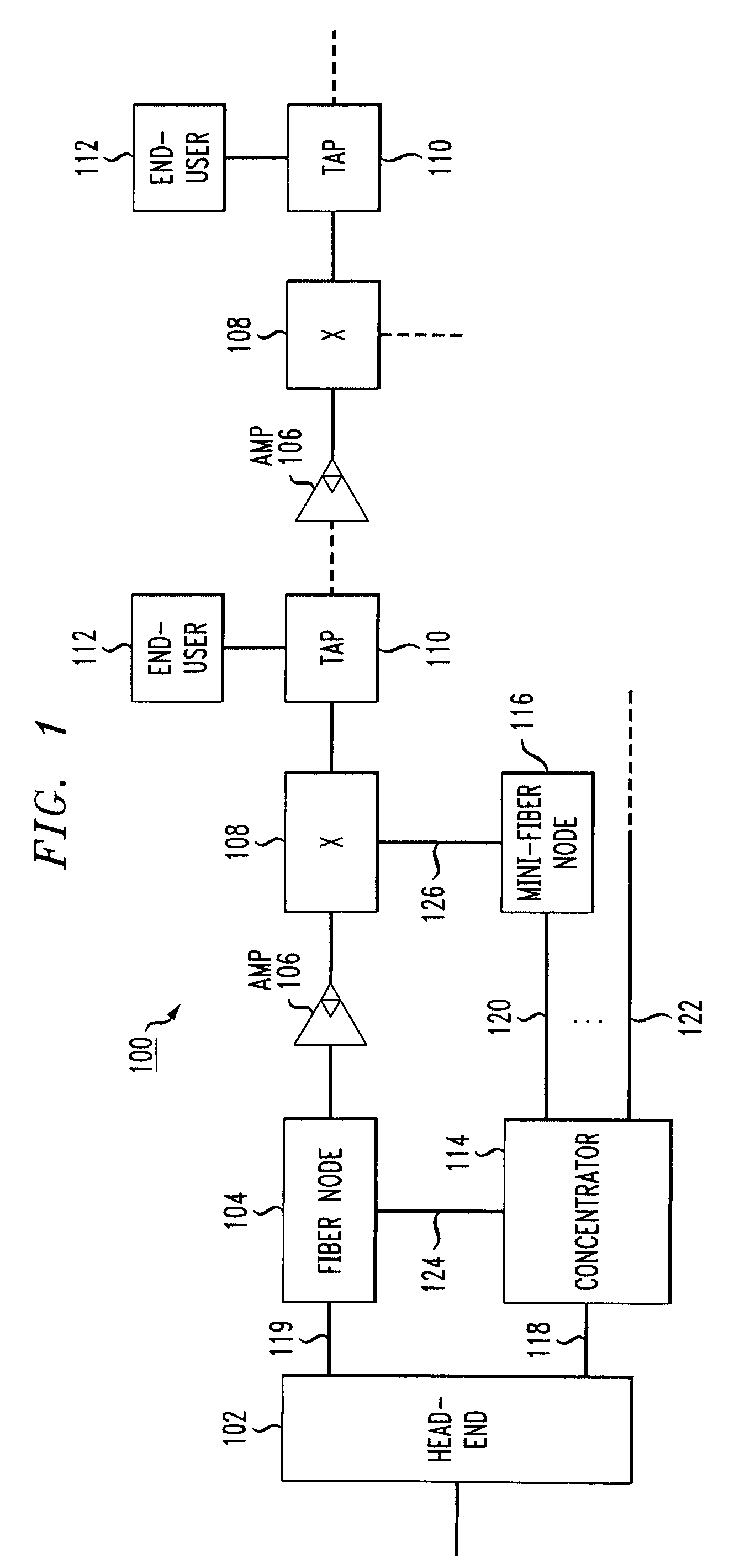
[0006]This invention provides a new architecture for a communication system between head-ends and end-users which expands capacity, simplifies transmission and operation, increases reliability and reduces cost of the communication system. A concentrator receives communication signals from a head-end and forwards the received communication signals to either one or more fiber nodes and one or more mini-fiber nodes. End-users communicate with the fiber nodes and mini-fiber nodes via wired connections such as coaxial lines. The connection to the head-end is via a small number of optical fibers (preferably one or two) while a much larger number of mini-fiber nodes may be serviced where a connection to each of the mini-fiber nodes is via one or more optical fibers that provide full duplex communication.
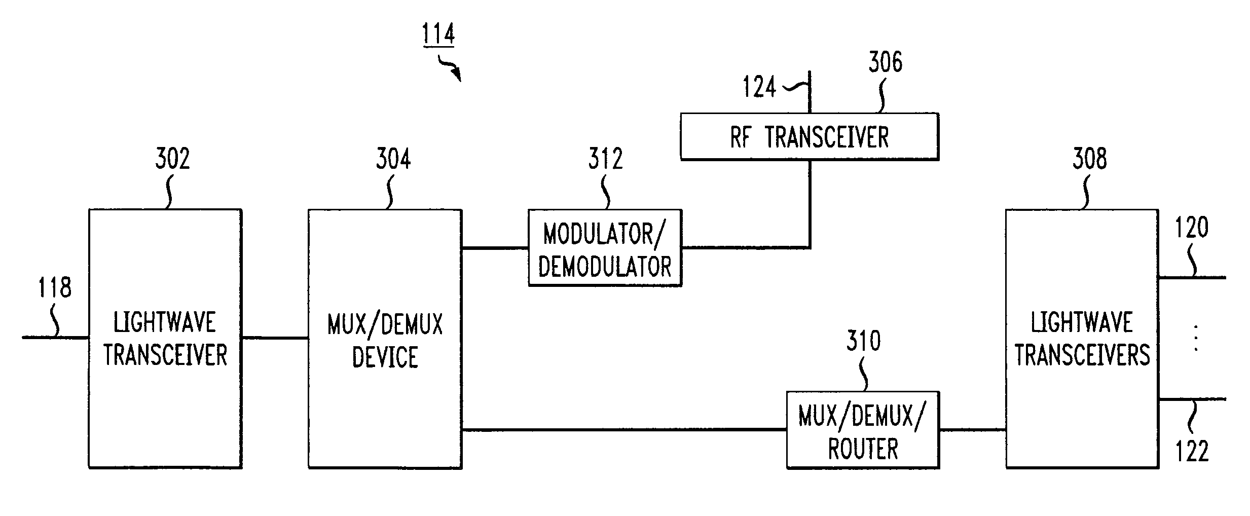
[0010]The concentrator also receives communication signals from end-users through the mini-fiber nodes that may be destined to other end-users also connected to the mini-fiber nodes. In this situation, the concentrator may include a router that routes the communication signals among mini-fiber nodes without forwarding the information to the head-end. In this way, communication traffic between the concentrator and the head-end is reduced with corresponding increase in efficiency.
[0011]Reliability is increased because the concentrator reduces the number of optical fibers required to be connected to the head-end. This shortens the mean-time-to-repair (MTTR) and also reduces cost of the communication system.

Problems solved by technology

With increasing need for greater capacity, current systems are stressed to their limits.

Method used


Image

  • Fiber/wired communication system
  • Fiber/wired communication system
  • Fiber/wired communication system

Examples


Embodiment Construction

[0025]FIG. 1 shows an exemplary block diagram of a communication system 100 between a head-end 102 and end-users 112. A first downstream signal such as broadcast information is transmitted from the head-end 102 to a fiber node 104. The fiber node 104 forwards the broadcast information to the end-users 112 via amplifiers 106 and taps 110. The end-users 112 may communicate with the head-end via an upstream channel through the taps 110, the amplifiers 106 (upstream indicated by the smaller triangle within the larger triangle) and the fiber node 104.

[0026]Analog communication signals between the head-end and the fiber node 104 are transmitted via an optical fiber(s) 119. The communication signals may include first downstream traditional cable television broadcast signals, for example. First upstream signals from the end-users 112 may be transmitted to the head-end via a band different than a band for the first downstream broadcast signals.

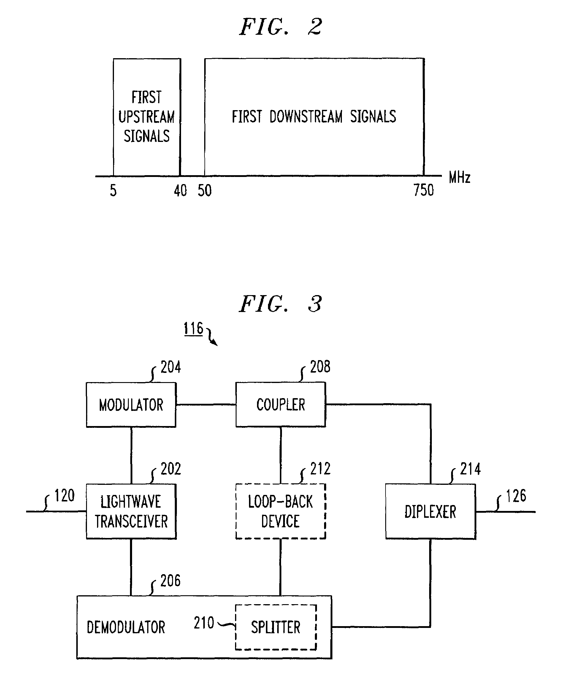
[0027]FIG. 2 shows an exemplary band allocation ...


PUM


Abstract

A communication system between head-ends and end-users is provided which expands bandwidth and reliability. A concentrator receives communication signals from a head-end and forwards the received communication signals to one or more fiber nodes and / or one or more mini-fiber nodes. The concentrator demultiplexes / splits received signals for the mini-fiber nodes and the fiber nodes and forwards demultiplexed / split signals respectively. The mini-fiber nodes may combine signals received from the head-end with loop-back signals used for local medium access control prior to forwarding the signals to the end-users. Upstream data are received by the mini-fiber nodes and / or fiber node and transmitted to the concentrator. The concentrator multiplexes / couples the mini-fiber node and the fiber node upstream signals and forwards multiplexed / coupled signals to the head-end. Communication signals received from the mini-fiber nodes that are destined to other end-users also connected to the mini-fiber nodes may be routed by the concentrator without head-end interaction.

Description

[0001]This application is a continuation of U.S. non-provisional patent application Ser. No. 09 / 460,770, filed Dec. 14, 1999 now U.S. Pat. No. 6,654,563, entitled “Fiber / Wired Communication System.” This application also claims the benefit of priority to provisional application No. 60 / 120,373, filed Feb. 17, 1999, entitled “Fiber / Wired Communication System.” The prior applications noted above are each incorporated herein by reference in its entirety.BACKGROUND OF THE INVENTION[0002]1. Field of Invention[0003]This invention relates to a communication system that includes fiber optic and wired mediums.[0004]2. Description of Related Art[0005]Cable communication systems use optical fibers to transmit information between a head-end and a fiber node and use coaxial cable to transmit information between the fiber node and end-users. With increasing need for greater capacity, current systems are stressed to their limits. Thus, there is need for new technology to increase capabilities of co...

Claims


Application Information

Patent Timeline
Patent Type & Authority Patents(United States)
IPC IPC(8): H04J14/00H04B10/12H04N7/173H04N7/22
CPCH04B10/25751H04N7/22H04N7/17309
Inventor DARCIE, THOMAS EDWARDDESAI, BHAVESH N.GNAUCK, ALAN H.LU, XIAOLINWOODWARD, SHERYL LEIGH
Owner AMERICAN TELEPHONE & TELEGRAPH CO
Learn More