Torque wrench with force indication

a torque wrench and force technology, applied in the direction of wrenches, screwdrivers, manufacturing tools, etc., can solve the problems of increasing the possibility of infection, and increasing the risk of bone loss and implant failure,

Pending Publication Date: 2022-06-23
JIRIES YOUSEF
View PDF0 Cites 0 Cited by
  • Summary
  • Abstract
  • Description
  • Claims
  • Application Information

AI Technical Summary

Benefits of technology

The present invention is a torque wrench that accurately indicates the torque applied to an object. This is done by measuring the force applied by the user on the torque wrench. By measuring the force, the torque measurement is simple and direct, without needing any calibration. The force sensors are located at the end of the torque wrench that is opposite to the wrench head, which allows for a relatively low force to result in a relatively large torque at the rotating axis. The pressure-sensitive material used in the torque wrench may include a combination of piezoelectric and piezochromic materials, which produce a dual signal that includes an electric current and a color-change indication upon application of a certain force. This may increase the credibility of the measured forces, which is translated to the real applied torque by the torque wrench.

Problems solved by technology

For example, in the dental world, tightening an abutment to an implant too low may leave a gap, which increases the bacterial infiltration, increasing the possibility for infection, bone loss and implant failure.
On the other hand, inserting the implant in higher torque than suggested by the manufacturer might induce stress on the bone and cause a bone resorption.
In addition, it can cause a breakage of the screw that tightens the implant / abutment complex, causing a failure of the prosthetic rehabilitation.
Since it is very difficult to obtain a direct measurement of the torque that is applied by a torque wrench, there are many different tools and methods that measures the torque indirectly.
These tools have limited accuracy, which may be not sufficiently accurate for obtaining the desired medical result.
Furthermore, these tools are typically required to be repeatedly calibrated.

Method used


Image

  • Torque wrench with force indication
  • Torque wrench with force indication
  • Torque wrench with force indication

Examples


Embodiment Construction

[0059]The following figures are provided to exemplify embodiments and realization of the invention of the present disclosure.

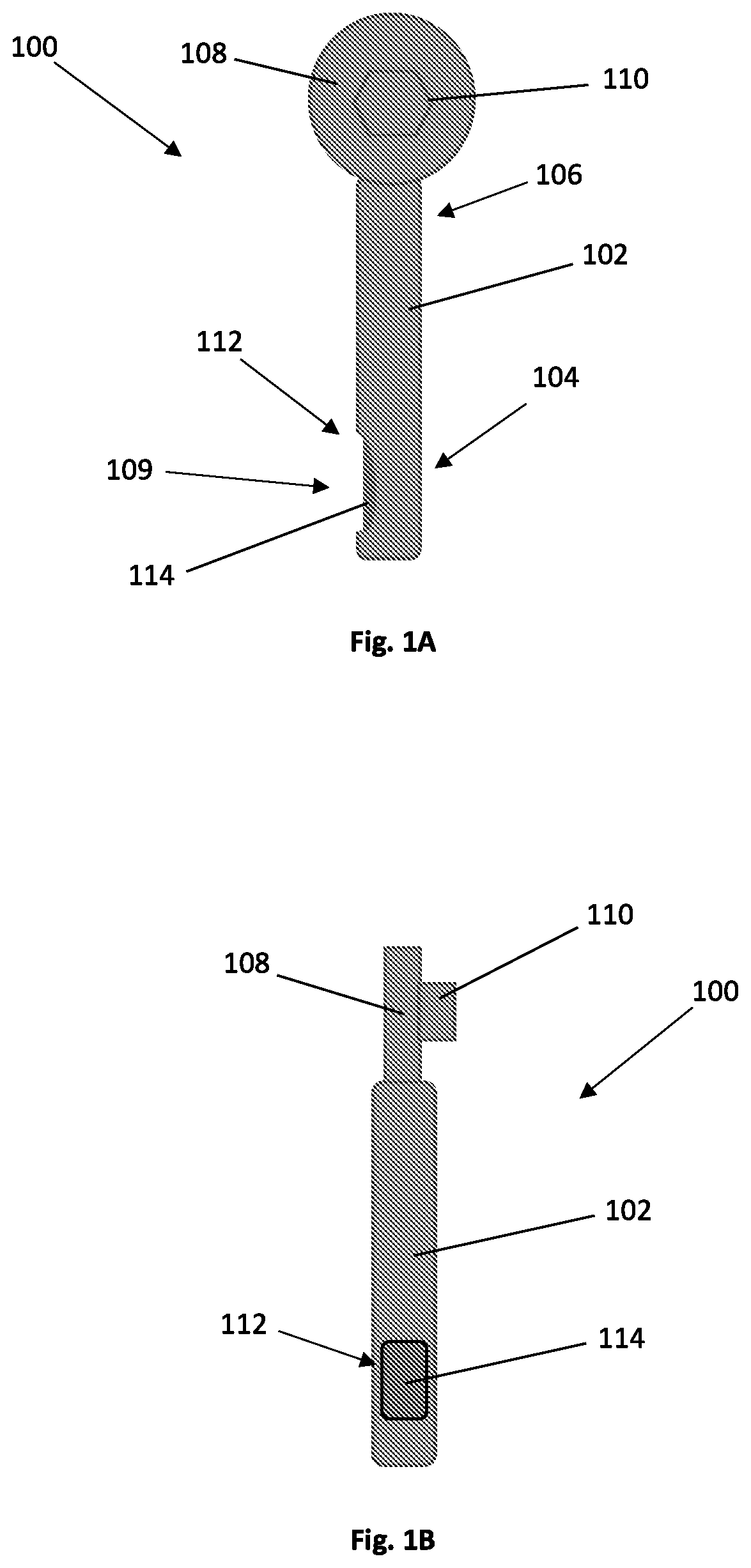
[0060]Reference is first made to FIGS. 1A-1B, which is are schematic illustrations of an embodiment of a torque wrench according to the present disclosure, wherein FIG. 1A is bottom view and FIG. 1B is a side view. The torque wrench 100 includes an elongated body 102, extending between a proximal end 104 and a distal end 106. A wrench head unit 108 is coupled to the distal end 106 of the elongated body 102 such that the wrench head unit 108 and the elongated body 102 constitute the torque wrench 100. The wrench head unit 108 may be integral with the elongated body 102 or detachably coupled therewith. The wrench head unit 108 includes a fastening portion 110 that is configured to be coupled with a screwing element (not shown) that is configured to engage with an object to be fastened, and fasten it upon application of torque thereon. In some embodiments, the fa...


PUM


Abstract

Provided is a torque wrench, or Mechanical Torque Limiting Device (MTLD), that is configured to accurately indicate the torque applied thereby on the object (or vice versa). The measurement of the torque is carried out by incorporating a pressure sensitive material in a gripping portion that is associated with the body of the torque wrench. The pressure sensitive material is configured to exhibit a signal upon application of force thereof. The signal can be an electric-based, color-based, motion-based (vibrations) or audio-based indication.

Description

TECHNOLOGICAL FIELD[0001]The present disclosure is in the field of hand-held tools, in particular tools for tightening objects, such as a Mechanical Torque Limiting Device (MTLD).BACKGROUND ART[0002]References considered to be relevant as background to the presently disclosed subject matter are listed below:[0003]US 2008 / 074643[0004]US 2017 / 354403[0005]WO 17 / 025406[0006]WO 17 / 025408[0007]TW 201701840[0008]US 2016 / 144492[0009]US 2012 / 101515[0010]WO 12 / 118487[0011]US 2010 / 294094[0012]Acknowledgement of the above references herein is not to be inferred as meaning that these are in any way relevant to the patentability of the presently disclosed subject matter.BACKGROUND[0013]There are many situations that require tightening of an object, such as screws and bolts, with an accurate torque value. A deviation from the exact torque value may have a great impact. For example, in the dental world, tightening an abutment to an implant too low may leave a gap, which increases the bacterial infi...

Claims


Application Information

Patent Timeline
Patent Type & Authority Applications(United States)
IPC IPC(8): B25B23/142B25G1/10
CPCB25B23/1425B25G1/105B25B13/462B25B23/142
Inventor JIRIES, YOUSEF
Owner JIRIES YOUSEF
Why Eureka
Try Eureka