
Smart coating system with chemical taggants for coating condition assessment

a coating condition and intelligent technology, applied in the direction of wind motors with parallel air flow, wind motors with perpendicular air flow, liquid fuel engine components, etc., can solve the problems of high inefficiency, time-consuming and costly, radioactive materials in water stream will not be released to the environment, and the technique cannot be applied to gas turbines

Inactive Publication Date: 2003-06-26
GENERAL ELECTRIC CO
View PDF0 Cites 50 Cited by
  • Summary
  • Abstract
  • Description
  • Claims
  • Application Information

AI Technical Summary

Benefits of technology

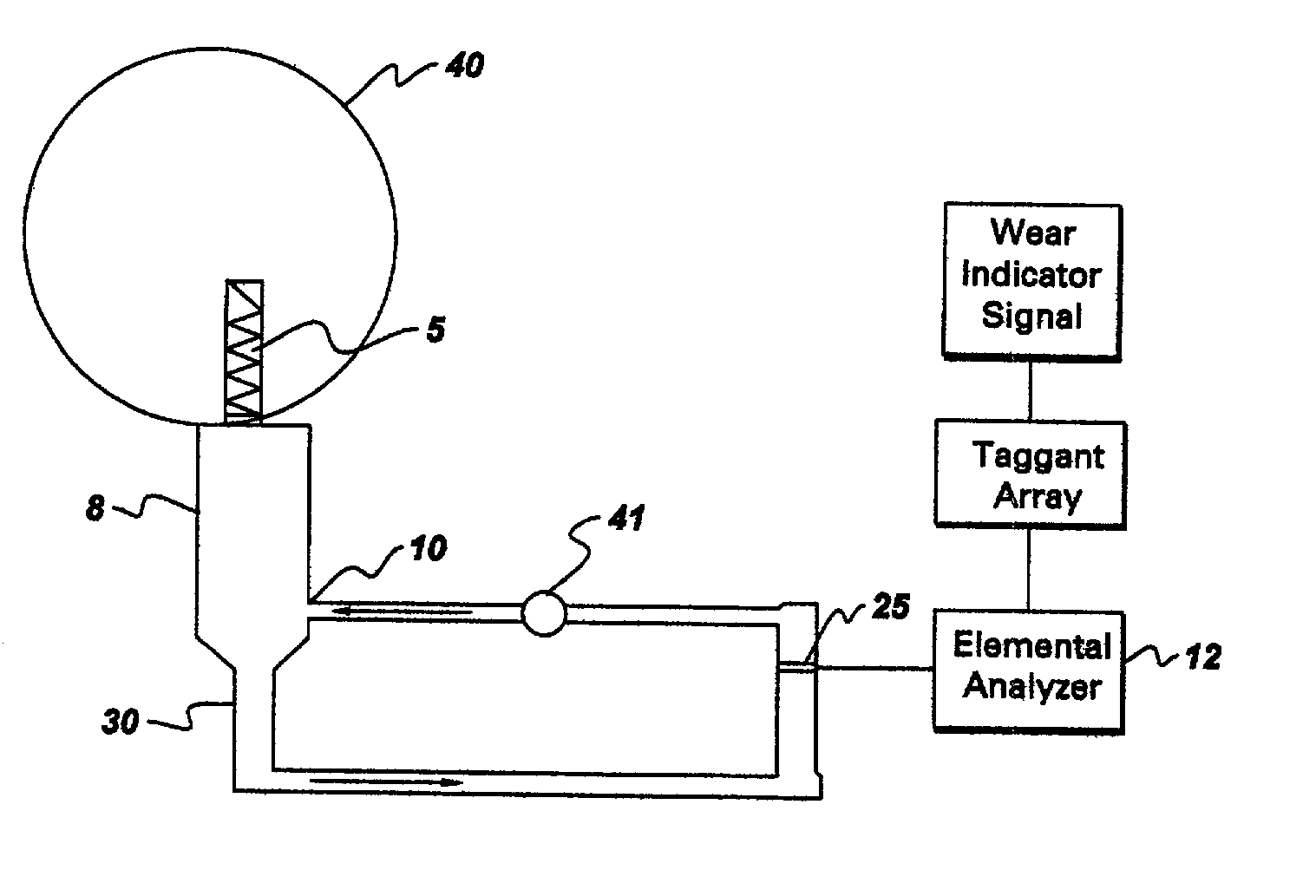
[0019] The present inventors discovered an in situ assessment method in which coatings on gas turbine parts are doped with unique taggants which, when detected in downstream exhaust gases, will indicate precisely which set of parts are deteriorating, and to what level. This provides improved knowledge of the coated part's condition and alters the replacement and repair strategy, thereby improving subsequent up-time of the machine. Moreover, these smart coatings can indicate their state of wear and / or damage while the machine that contains them is in full operation.
[0021] The preferred embodiments of the invention also provide an online method of assessing wear and damage that has occurred to gas turbine parts. "Online" means that the assessment can be determined without interrupting the operation of the turbine. The preferred embodiments of invention include smart coatings containing chemical taggants which serve as online indicators of the degree of wear and damage of gas turbine section parts.

Problems solved by technology

However, this process is highly inefficient, time consuming, and costly due to turbine shut-down and maintenance.
However, the above techniques can only be applied to steam turbines, which are closed systems, so that radioactive materials in the water stream will not be released to the environment.
The technique cannot be applied to gas turbines because the exhaust is released into the air, and radioactive elements will be detrimental to the environment.
These methods are unable to focus on individual parts because they do not take into account the circumstances that the parts installed in a particular turbine actually encounter, such as foreign object damage, variation of operating conditions from site to site, and occasional overfiring of the turbine.

Method used


Image

  • Smart coating system with chemical taggants for coating condition assessment
  • Smart coating system with chemical taggants for coating condition assessment
  • Smart coating system with chemical taggants for coating condition assessment

Examples


Embodiment Construction

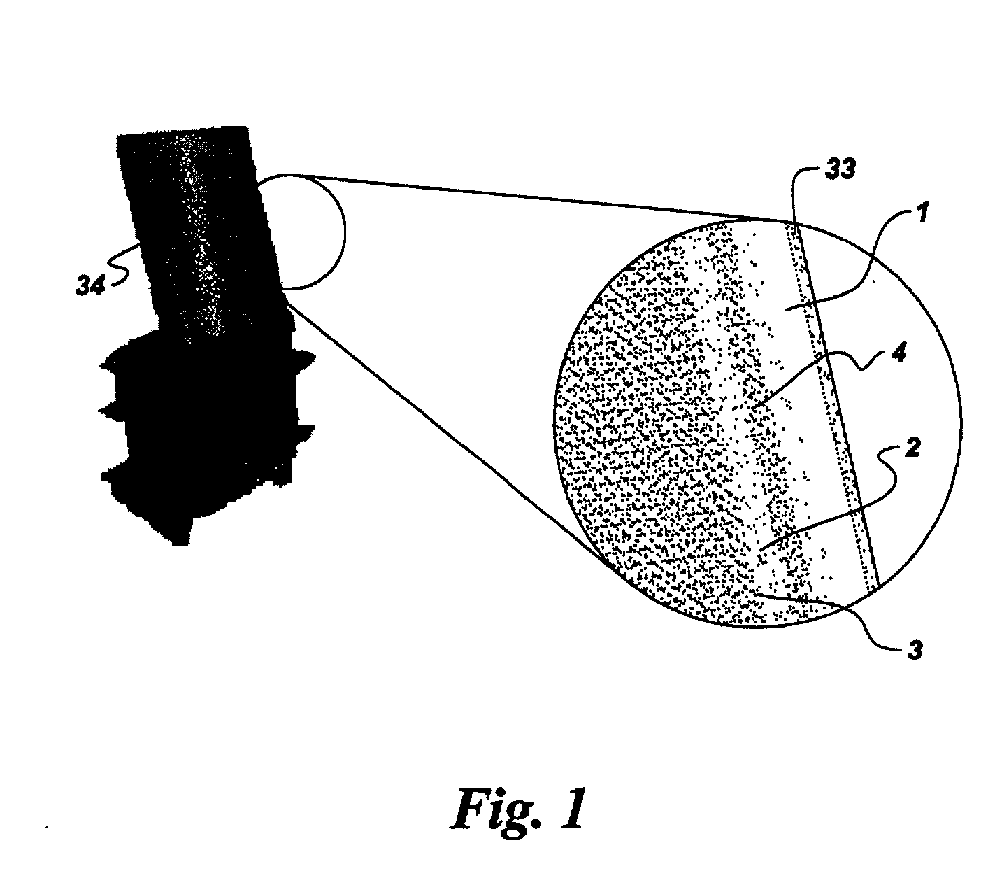
[0053] FIG. 7 is a cross sectional view of a sample component substrate with an environmentally resistant coating comprising an Ru taggant. The coating composition is: 35.7% Co, 32% Ni, 22% Cr, 10% Al, and 0.3% Y in weight percent. The layer comprising Ru taggant has a composition of 26.8% Ni, 46.4% Ru, 4.7% Cr, and 22.1% Al in weight percent. The substrate is a superalloy has a composition of: 60.39% Ni, 9.5% Co, 14.0% Cr, 3.0% Al, 4.9% Ti, 2.8% Ta, 3.8% W, 1.5% Mo, 0.1% C, and 0.01% B in weight percent. The coating layers were deposited using the HVOF method well known in the art. FIG. 7 depicts the as-deposited condition.

[0054] After the sample was exposed at 1150.degree. C. for 450 hours, the coating microstructure is shown in FIG. 8. It can be seen that there was very little growth of the Ru-containing layer, demonstrating stability of the taggant layer with respect to high temperature exposure. When the coating deteriorates by oxidation and wear, and deterioration reaches loca...


PUM

PropertyMeasurementUnit
Temperatureaaaaaaaaaa

Abstract

A on-line method is provided for detecting wear and / or damage to gas turbine parts. Preferred embodiments of the invention provide a gas turbine comprising parts with smart coatings and collection and detection means to measure wear and erosion of gas turbine parts. In other preferred embodiments, smart coatings are provided comprising chemical taggants that can be collected and detected downstream, thus providing an on-line or in situ evaluation technology for wear and damage to gas turbine parts.

Description

BACKGROUND OF INVENTION[0001] The invention relates to an on-line or in-situ method of assessing wear and / or damage that has occurred to turbine parts. The invention also relates to a gas turbine comprising parts with smart coatings and collection and detection means to measure wear and erosion of gas turbine parts.[0002] The current industry practice for determining wear and damage of gas turbine parts is schedule-based shutting down of a turbine and physically examining parts at predetermined intervals. However, this process is highly inefficient, time consuming, and costly due to turbine shut-down and maintenance. In response, general on-line or in-situ methods have been developed for detecting wear-out of outer surfaces of wear-susceptible parts.[0003] For example, Blatchley and coworkers (C. C. Blatchley and R. J. Bricault Jr., in Tribological Mecharnims & Wear Problems in Materials, ASM International, Metals Park, Ohio, 1987, pp. 95-100 and C. C. Blatchley and P. G. Loges, in ...

Claims


Application Information

Patent Timeline
IPC IPC(8): C23C28/00C23C30/00F02C9/00
CPCC23C30/00F05D2260/80Y02T50/67F02C9/00Y02T50/60
Inventor ZHAO, JI-CHENGRUUD, JAMES ANTHONYTKACZYK, JOHN ERICRITTER, ANN MELINDAJACKSON, MELVIN ROBERTTIEMANN, JEROME JOHNSON
Owner GENERAL ELECTRIC CO
Learn More