Bidirectional insulating dc-dc converter, control apparatus therefor, and operating method thereof

a dc-dc converter and bi-directional technology, applied in the direction of electric variable regulation, process and machine control, instruments, etc., can solve the problems of increasing the size of a product and increasing the cost of materials, so as to reduce the reduction of efficiency, reduce power conversion loss, and improve efficiency

Pending Publication Date: 2022-06-16
HYUNDAI MOBIS CO LTD
View PDF32 Cites 0 Cited by
  • Summary
  • Abstract
  • Description
  • Claims
  • Application Information

AI Technical Summary

Benefits of technology

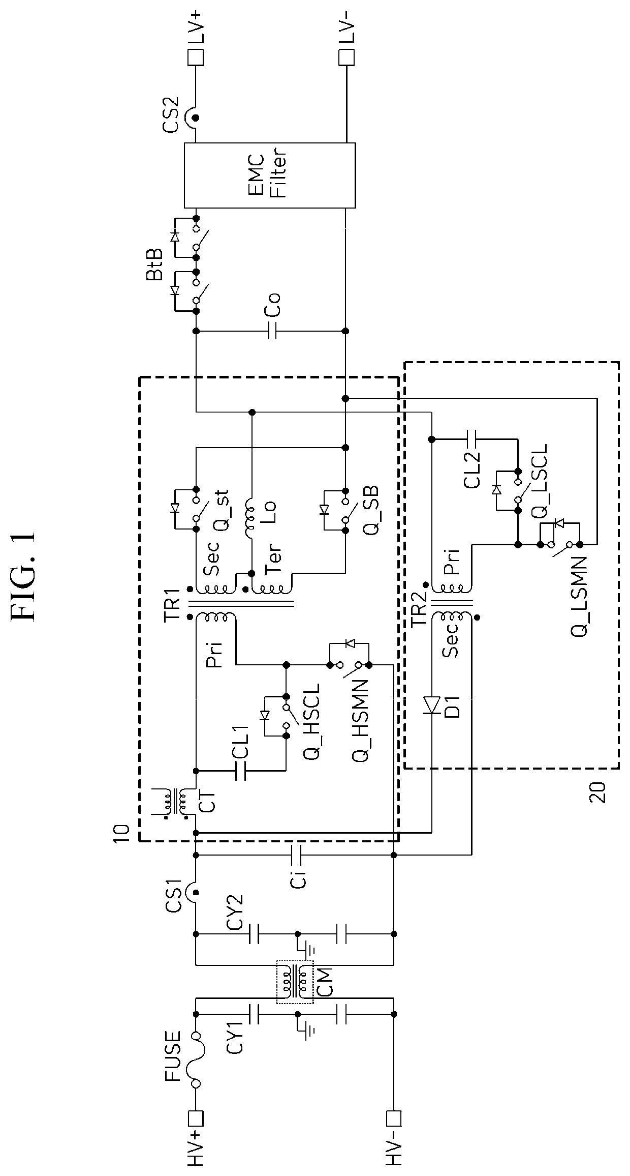
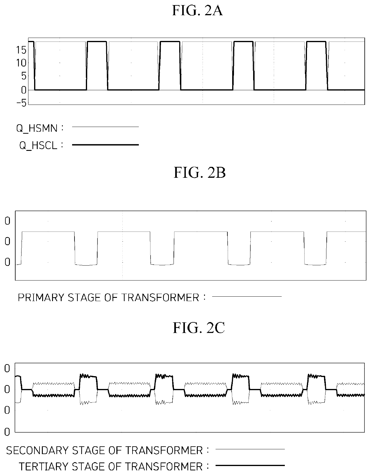
[0009]To solve the problems, the bidirectional insulating DC-DC converter shares high / low voltage terminals, a cooling passage, a housing, and a control circuit (a control board), and two independent step-down circuit and step-up circuit are formed in parallel to perform a bidirectional DC power conversion. The step-down circuit may be formed as an active clamp forward converter circuit, and the step-up circuit may be formed as an active clamp flyback converter circuit. A forward converter may be generally more efficient at a light load with a low output and may be consistent with a profile of a use amount of a main load in the vehicle and suitable for reducing power conversion loss.
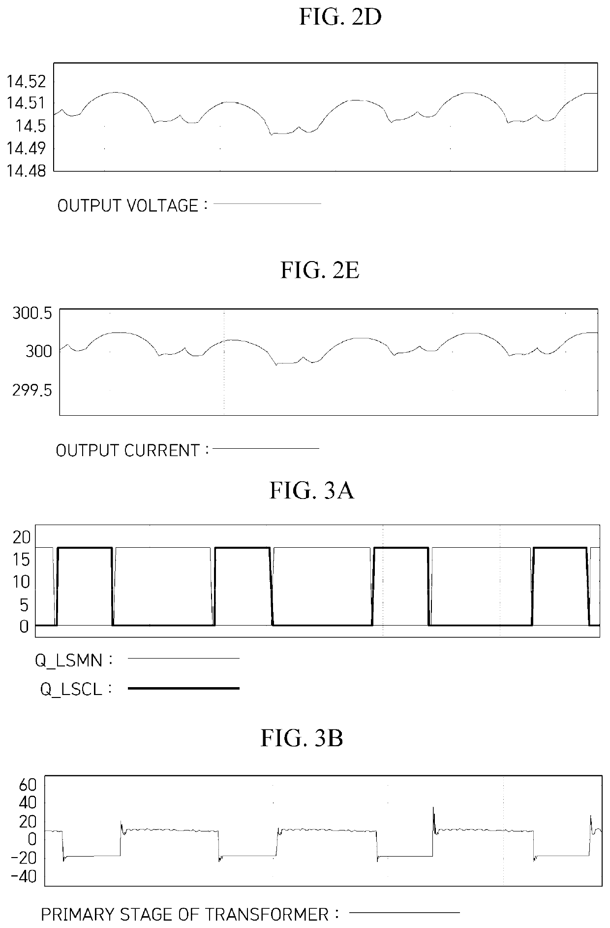
[0010]In addition, in the step-down circuit of the present disclosure, a rectifying diode in low voltage stage used in the existing forward converter may be replaced with a large current type semiconductor switch element, such as a metal oxide semiconductor field effect transistor (MOSFET), to decrease a reduction in efficiency even in a situation in which an output current is large. Accordingly, high efficiency, which is an important factor in an eco-friendly vehicle, may be satisfied.
[0011]In addition, one control board controls the step-down circuit and the step-up circuit, the ease of control is high, and a signal can be used in common when a logic is formed, and thus costs of components and a probability of malfunction may be reduced.

Problems solved by technology

In this case, there is a disadvantage in that a size of a product should be increased and a material cost also becomes expensive.

Method used


Image

  • Bidirectional insulating dc-dc converter, control apparatus therefor, and operating method thereof
  • Bidirectional insulating dc-dc converter, control apparatus therefor, and operating method thereof
  • Bidirectional insulating dc-dc converter, control apparatus therefor, and operating method thereof

Examples


Embodiment Construction

[0020]Advantages and features of the present disclosure and methods for achieving them will be made clear from exemplary embodiments described in detail below with reference to the accompanying drawings. However, the present disclosure is not limited to the embodiments described below and may be implemented in various other forms. The embodiments are provided such that this disclosure will be thorough and complete and will fully convey the scope of the present disclosure to those skilled in the art to which the present disclosure pertains, and the present disclosure is defined only by the scope of the appended claims. In addition, terms used herein are for the purpose of describing the embodiments and are not intended to limit the present disclosure. In this disclosure, the singular forms include the plural forms unless the context clearly dictates otherwise. The term “comprise” or “comprising” used herein does not preclude the presence or addition of one or more other elements, ste...


PUM


Abstract

The bidirectional insulating DC-DC converter shares high/low voltage terminals, a cooling passage, a housing, and a control board, and two independent step-down circuit (10) and step-up circuit (20) are formed in parallel to perform a bidirectional DC power conversion. A high voltage applied from a high voltage battery HV is stepped down through the step-down circuit (10) and output to a low voltage battery LV. On the other hand, a low voltage applied from the low voltage battery LV is stepped up through the step-up circuit (20) and output to the high voltage battery HV. The step-down circuit (10) is formed as an active clamp forward converter circuit, and the step-up circuit (20) is formed as an active clamp flyback converter circuit.

Description

CROSS-REFERENCE TO RELATED APPLICATION[0001]This application claims the benefit of priority to Korean Patent Application No. 10-2020-0175909, filed on Dec. 15, 2020 in the Korean Intellectual Property Office, the entire disclosure of which is incorporated herein by reference for all purposes.BACKGROUND1. Technical Field[0002]The present disclosure relates to a bidirectional insulating DC-DC converter, and more particularly, to a bidirectional insulating DC-DC converter separately including a step-down circuit and a step-up circuit, a control apparatus therefor, and operating method thereof.2. Discussion of Related Art[0003]Low voltage DC-DC converters (LDC), which are DC power supplies applied to eco-friendly vehicles (hybrid electric vehicles (HEV), plug-in hybrid electric vehicles (PHEV), EV, and fuel cell vehicles (FCV)) by replacing an alternator of an internal combustion engine, are essential devices which receive high voltage battery power (for example, in a range of 180 V to ...

Claims


Application Information

Patent Timeline
Patent Type & Authority Applications(United States)
IPC IPC(8): H02M3/335H02M1/00H02J7/00
CPCH02M3/33584H02M1/44H02J7/007H02M1/0009H02M1/40H02M1/342H02M1/0003H02M3/285H02M3/33569H02M3/33546H02M1/32H02M1/36H02M3/003Y02T10/92B60L53/22B60L55/00B60L2210/12B60L2210/14B60L2240/529H02J7/342H02J2207/20H02M3/3353H02M3/33538B60L2210/10B60L53/20
Inventor KIM, DU HOCHOI, DEOK KWANHEO, MINKIM, KANG MINJEON, SOO MINLEE, A RAKIM, WON GONPARK, JI HOONSHIM, HYUN WOOBANG, TAE HO
Owner HYUNDAI MOBIS CO LTD
Why Eureka
Try Eureka