Cutting tool with directed fluid flow to facilitate chip evacuation

a cutting tool and fluid flow technology, applied in the field of cutting tools, can solve problems such as difficulty in evacuating chips from cutting zones, and achieve the effects of improving the efficiency of fluid flow, facilitating chip evacuation, and facilitating chip evacuation

Active Publication Date: 2022-06-09
KENNAMETAL INC
View PDF5 Cites 0 Cited by
  • Summary
  • Abstract
  • Description
  • Claims
  • Application Information

AI Technical Summary

Benefits of technology

This patent is about a cutting tool that solves the problem of evacuating chips from the cutting zone. The tool has a fluid dynamic structure with arms that function both mechanically and fluid dynamically to evacuate chips. The front cutting ring and the rear cutting ring each have a leading and trailing support arm with a cutting head. The fluid dynamic structure on the arms directs fluid flow towards the rear of the tool, which improves chip evacuation during a cutting operation. The technical effects of this patent are improved chip evacuation, reduced wear and tear, and improved tool performance.

Problems solved by technology

It has been observed that a reamer, for example, may have difficulties evacuating chips from the cutting zone, particularly when machining a blind hole.

Method used


Image

  • Cutting tool with directed fluid flow to facilitate chip evacuation
  • Cutting tool with directed fluid flow to facilitate chip evacuation
  • Cutting tool with directed fluid flow to facilitate chip evacuation

Examples


Embodiment Construction

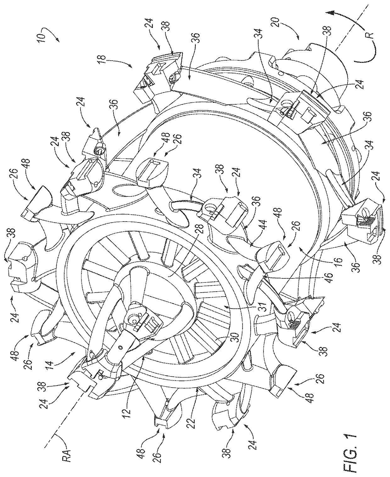
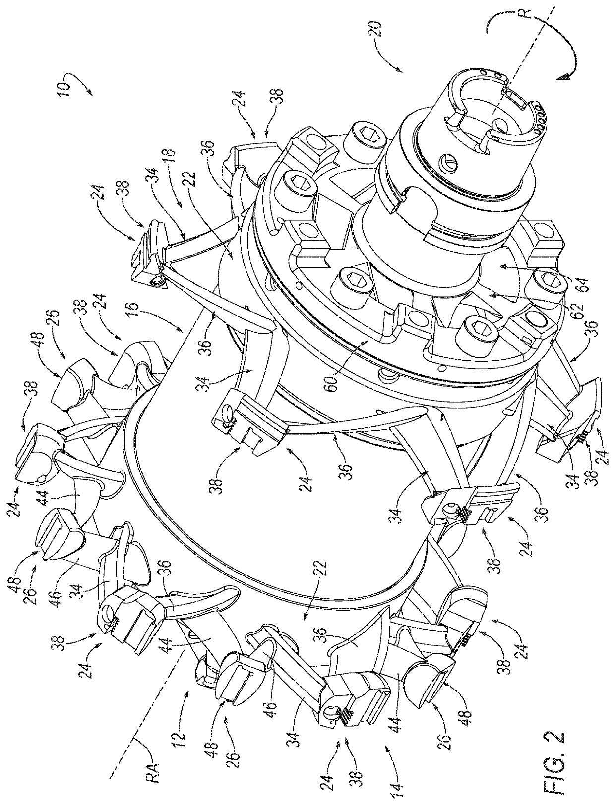
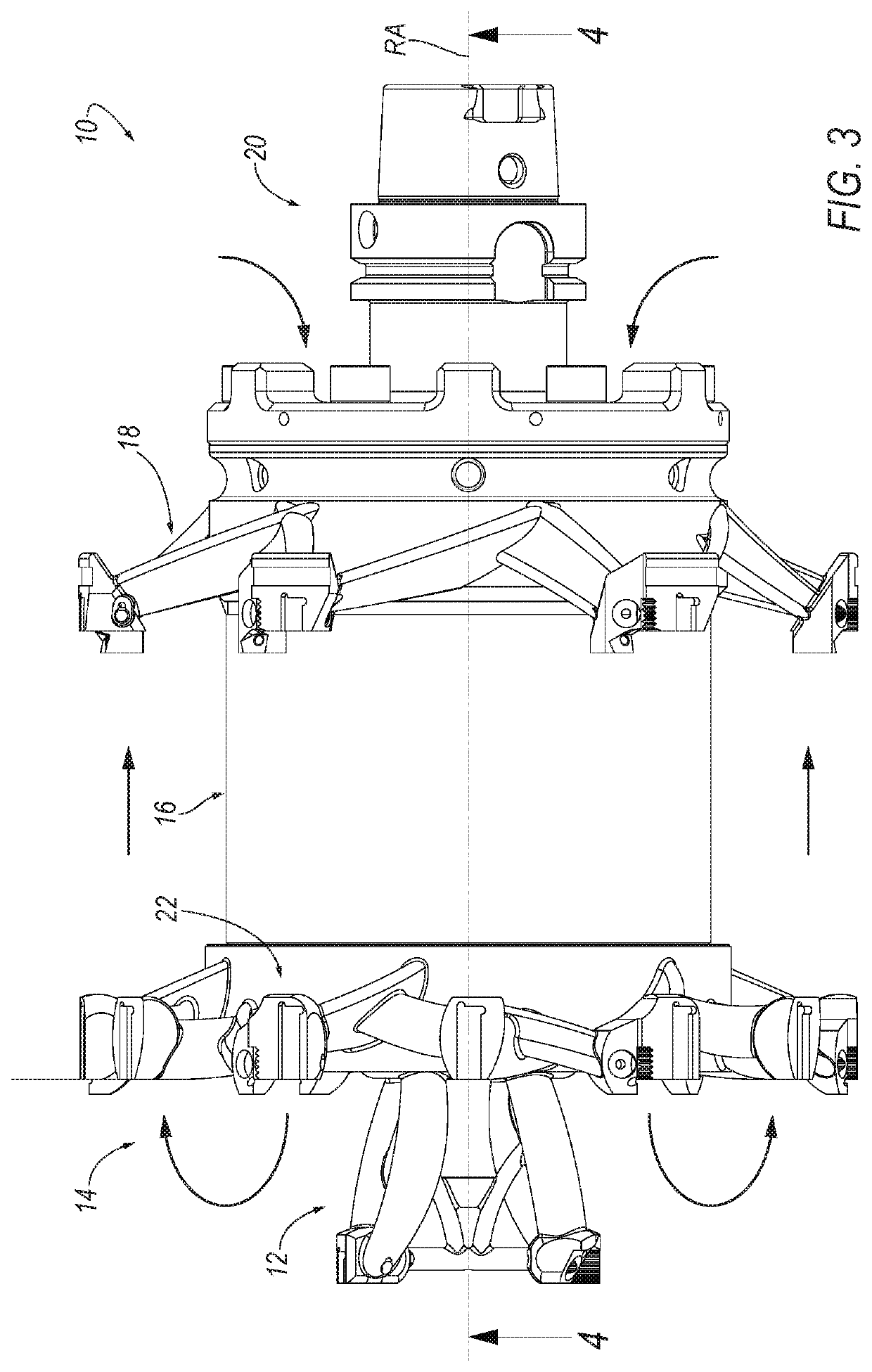
[0027]Referring now to FIGS. 1-5, a cutting tool 10 is shown according to an embodiment of the invention. In the illustrated embodiment, the cutting tool comprises a reamer with directed fluid flow that rotates in the direction, R, about a central, rotational axis, RA, during operation. Although the cutting tool 10 comprises a reamer in the illustrated embodiment, it should be appreciated that the principles of the invention can be applied to any cutting tool for cutting operations, such as a milling cutter, and the like. In addition, the description herein of specific applications should not be a limitation on the scope and extent of the use of the cutting tool.

[0028]Directional phrases used herein, such as, for example, left, right, front, back, top, bottom and derivatives thereof, relate to the orientation of the elements shown in the drawings and are not limiting upon the claims unless expressly recited therein. Identical parts are provided with the same reference number in all ...


PUM


Abstract

A cutting tool, such as a reamer, includes a rear machine connection member, a center tube, a front cutting ring, and a rear cutting ring. The front cutting ring includes a sleeve member and one or more cutting head assemblies. Each cutting head assembly includes at least one support arm extending radially outwardly from a rotational axis, RA, of the cutting tool, and a cutting head supported by the at least one support arm. The at least one support arm of the cutting head assembly defines a fluid dynamic structure for directing fluid flow in a desired direction to facilitate chip evacuation during a cutting operation. The fluid dynamic structure can be an airfoil, a turbine blade, or similar structure that produces a directed fluid flow.

Description

CROSS NOTING TO RELATED APPLICATIONS[0001]This application is related to application Ser. No. 16 / 557,533, filed on Aug. 30, 2019, the entire contents of which are incorporated herein by reference.FIELD OF THE DISCLOSURE[0002]In general, the invention relates to cutting tools, and more particularly, to a lightweight cutting tool, such as a reamer, and the like, with a fluid dynamic structure, such as airfoil-shaped arms, that directs the flow of fluid in a desired direction to facilitate chip evacuation during a cutting operation.BACKGROUND OF THE DISCLOSURE[0003]During a cutting operation, it is essential to remove chips from the cutting zone. It has been observed that a reamer, for example, may have difficulties evacuating chips from the cutting zone, particularly when machining a blind hole.SUMMARY OF THE DISCLOSURE[0004]The problem of the evacuation of chips from the cutting zone in a cutting tool, such as a reamer, and the like, can be solved by providing one or more arms with a...

Claims


Application Information

Patent Timeline
Patent Type & Authority Applications(United States)
IPC IPC(8): B23D77/00
CPCB23D77/00B23D2277/30B23D77/006B23D2277/46B33Y80/00
Inventor SEMNISKY, LOGAN M.BOOKHEIMER, ALAN J.GRILLENBERGER, INGOSCHMID, DOMINIK
Owner KENNAMETAL INC
Why Eureka
Try Eureka