
Wilkinson divider

Pending Publication Date: 2022-05-26
TEKNOLOGIAN TUTKIMUSKESKUS VTT OY
View PDF0 Cites 0 Cited by
  • Summary
  • Abstract
  • Description
  • Claims
  • Application Information

AI Technical Summary

Benefits of technology

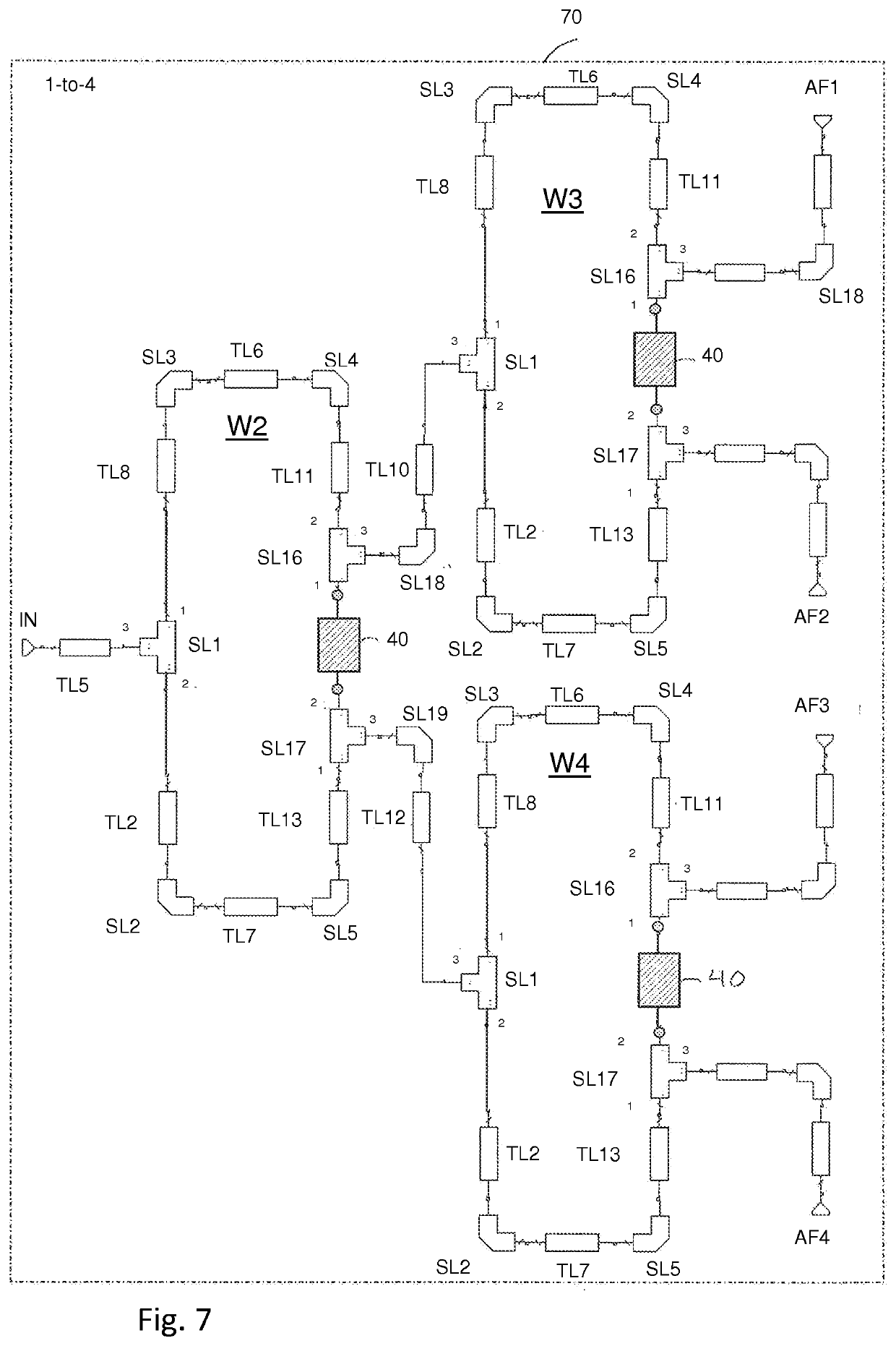
The invention provides a new design for a Wilkinson divider, a component used in millimeter-wave networks, that is cost-effective and easy to implement. The design includes a carrier substrate, transmission lines, and an isolation resistor integrated into a monolithic microwave integrated circuit (MMIC) chip. The design can be used in a signal distribution network with multiple outputs. The invention also provides a hybrid millimeter-wave device that includes the new Wilkinson divider design and a first and second input metal pad for mounting the device on a carrier substrate. The design includes a first parallel resonant circuit and a second parallel resonant circuit to compensate for parasitic capacitances in the input metal pads. The invention also includes a monolithic microwave integrated circuit (MMIC) chip with a plurality of integrated isolation resistors and a plurality of pairs of input metal pads.

Problems solved by technology

Nevertheless, as the size of the array grows, the amount of routing and the size of the feeding network increases rapidly.
In one approach, the feeding network for the antenna arrays comprises stripline Wilkinson dividers on a. However, the challenge in the PCB environment is the implementation of the isolation resistor of the Wilkinson divider.
Discrete resistors, such SMD resistors at frequencies of 60 GHz and higher are expensive and for large arrays they might not be easily assembled.
However, a problem with of such on-chip power splitters is that they consume expensive MMIC area and additionally may lead to an extra power loss because of an additional wiring needed between the phased array cells.

Method used


Image

  • Wilkinson divider
  • Wilkinson divider
  • Wilkinson divider

Examples


Embodiment Construction

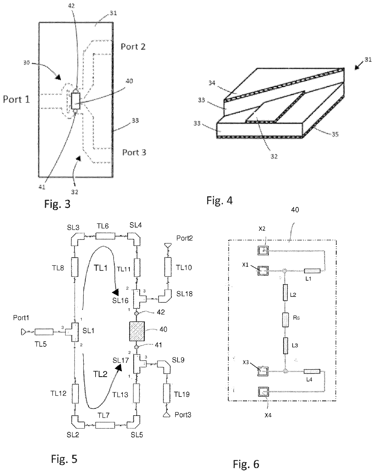
[0041]An aspect of the invention is a hybrid Wilkinson power divider or splitter which uses a carrier substrate or board for transmission line routing and a Monolithic Millimeter-wave Integrated Circuit (MMIC) technology for a resistor implementation. Transmission lines may be implemented in various alternative structures, such as microstrip line, stripline, coplanar waveguide (CPW). In the example embodiments, transmission lines are mostly implemented with microstrip lines, but embodiments of the invention are not restricted to the use of microstrip lines. The carrier substrate or board (which can also be referred to as an RF platform) suitable for embodiments of the invention can be manufactured using various different types of technologies, such as printed circuit board (PCB), Low-temperature cofired ceramic (LTCC), integrated possessive device (IPD), quartz wafer, etc. The exemplary embodiments herein will be described and illustrated using the PCB technology as an example witho...


PUM


Abstract

A hybrid millimeter-wave Wilkinson divider comprises an input port (1), a first output port (2), a second output port (3), and transmission lines connecting the input port (1) to the first and second output ports (2, 3) implemented by transmission lines in a carrier substrate (PCB, 31). An isolation resistor of the Wilkinson divider connected between the first and second output ports (2, 3) is integrated in a monolithic micro-wave integrated circuit (MMIC) chip (40) installed on the carrier substrate. On the MMIC chip the isolation resistor is connected between RF input metal pads. A compensation circuit for parasitic capacitances caused by the RF input metal pads is provided on the MMIC chip (40) so that the on-chip resistor appears as a pure resistance to the output ports (2, 3) of the Wilkinson divider on the carrier substrate (PCB, 31).

Description

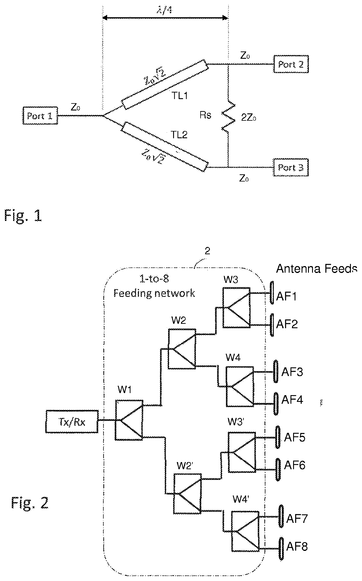
FIELD OF THE INVENTION[0001]The invention relates to millimeter wave devices, and particularly to millimeter wave Wilkinson dividers and millimeter wave phased arrays.BACKGROUND OF THE INVENTION[0002]The use of three-port power dividers is especially important for antenna array systems that utilize a power-splitting network, such a corporate or parallel feed system. The corporate is simply a device that splits power between n output ports with a certain distribution while maintaining equal path lengths from input to output ports. It can be implemented with n-way power splitters where three-port power dividers are commonly used.[0003]The Wilkinson power divider is a three-port network that is lossless when the output ports are matched; where only reflected power is dissipated. Input power can be split into two or more in-phase signals with the same amplitude. As illustrated in FIG. 1, the Wilkinson divider circuit may comprise two quarter wavelength (Δ / 4) transmission lines TL1 and T...

Claims


Application Information

Patent Timeline
IPC IPC(8): H01P5/16H01L23/66
CPCH01P5/16H01L2223/6683H01L2223/6627H01L23/66H01C7/006H01L27/00H01P5/02H01P5/19H01Q21/0006H01Q21/0075H01Q21/06H03H7/487
Inventor VARONEN, MIKKOLAMMINEN, ANTTI
Owner TEKNOLOGIAN TUTKIMUSKESKUS VTT OY
Learn More