
Endless hot-rolled strip production device and method for ferrite rolling

a production device and hot-rolled strip technology, which is applied in the direction of measuring devices, heat treatment apparatus, furniture, etc., can solve the problems of difficult implementation of ferrite rolling process, affecting the formability of materials, and difficult to implement ferrite rolling process, etc., to achieve precise temperature control, low rolling cost and energy consumption, and reasonable configuration of all components

Pending Publication Date: 2022-05-19
WUHAN IRON AND STEEL CO LTD
View PDF0 Cites 1 Cited by
  • Summary
  • Abstract
  • Description
  • Claims
  • Application Information

AI Technical Summary

Benefits of technology

The present invention relates to a device and method for producing high-quality, low-carbon or ultra-low carbon steel through ferrite rolling. The device has a simple production line, well-configured components, and precise temperature control, which helps to achieve consistent and high-quality products. The use of this device results in low production costs and energy consumption.

Problems solved by technology

Meanwhile, since the production line is mainly designed for the traditional austenitic rolling process, it is difficult to implement the ferrite rolling process.
However, due to the fine grain characteristics of products of thin slab continuous casting and continuous rolling process, a problem of a high strength generally exists in the production of low carbon and ultra-low carbon steel, which greatly affects formability of materials.
However, the existing thin slab continuous casting and continuous rolling production lines including CSP and ESP are still mainly designed according to the traditional austenitic rolling process, and the ferrite rolling process is difficult to implement.
By using the device for ferrite rolling, the product quality is high, and production cost and energy consumption are low.

Method used


Image

  • Endless hot-rolled strip production device and method for ferrite rolling
  • Endless hot-rolled strip production device and method for ferrite rolling

Examples


embodiment 1

[0029]The following chemical components and mass percent of low carbon steel are adopted: C: 0.05%, Si: 0.10%, Mn: 0.20%, P: 0.010%, S: 0.005%, N: 0.0040%, and the balance being Fe. A thickness of a continuously casting slab is 130 mm, a drawing speed is 4.5 m / min, a slab exits a continuous casting machine and then is subjected to high-pressure water rotating descaling at a descaling pressure of 20 MPa, and then directly enters a four-stand high reduction rough rolling unit for rolling (a reduction rate is 50%, 50%, 40% and 40%, respectively), a temperature of the slab before rough rolling is 1080° C., an intermediate billet after rough rolling has a thickness of 11.7 mm, an exit speed of 0.83 m / s and an exit temperature of 950° C., the intermediate billet enters a multifunctional cooling control device for high-pressure water descaling and controlled cooling, a length of the multifunctional cooling control device is 7 m, a high-pressure water descaling pressure is 35 MPa, and a coo...

embodiment 2

[0030]The following chemical components and mass percent of low carbon steel are adopted: C: 0.025%, Si: 0.07%, Mn: 0.10%, P: 0.010%, S: 0.004%, N: 0.0045%, and the balance being Fe. A thickness of a continuously casting slab is 70 mm, a drawing speed is 7 m / min, a slab exits a continuous casting machine and then is subjected to high-pressure water rotating descaling at a descaling pressure of 40 MPa, and then directly enters a four-stand high reduction rough rolling unit for rolling, a temperature of the slab before rough rolling is 1150° C., an intermediate billet after rough rolling has a thickness of 5 mm (a reduction rate is 60%, 50%, 40% and 40%, respectively), an exit speed of 1.6 m / s and an exit temperature of 980° C., the intermediate billet enters a multifunctional cooling control device for high-pressure water descaling and controlled cooling, a length of the multifunctional cooling control device is 5 m, a high-pressure water descaling pressure is 36 MPa, and a cooling s...

embodiment 3

[0031]The following chemical conponents and mass percent of ultra-low carbon steel are adopted: C: 0.0035%, Si: 0.03%, Mn: 0.08%, P: 0.009%, S: 0.003%, N: 0.0040%, and the balance being Fe. A thickness of a continuously casting slab is 110 mm, a drawing speed is 5.5 m / min, a slab exits a continuous casting machine and then is subjected to high-pressure water rotating descaling at a descaling pressure of 25 MPa, and then directly enters a four-stand high reduction rough rolling unit for rolling (a reduction rate is 55%, 50%, 46% and 40%, respectively), a temperature of the slab before rough rolling is 1200° C., an intermediate billet after rough rolling has a thickness of 8 mm, an exit speed of 1.26 m / s and an exit temperature of 970° C., the intermediate billet enters a multifunctional cooling control device for high-pressure water descaling and controlled cooling, a length of the multifunctional cooling control device is 7 m, a high-pressure water descaling pressure is 32 MPa, and ...


PUM

PropertyMeasurementUnit
Temperatureaaaaaaaaaa

Abstract

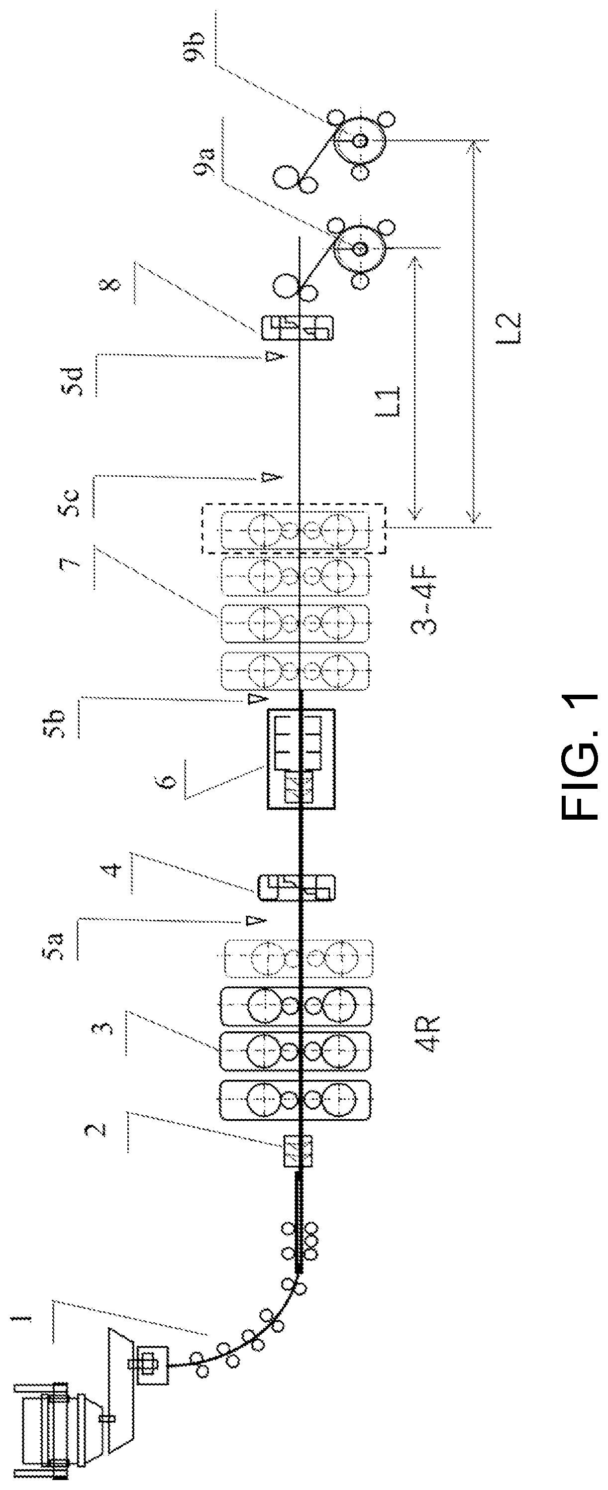
The device has a short production line, and all components are reasonably configured. A multifunctional cooling control device is adopted to integrate high-pressure water descaling and intermediate billet cooling functions, which is simpler and more efficient. Layout of a 4R+(3−4)F rolling mill, four thermos-detectors and short-distance underground coilers are use. The method includes the steps: carrying out continuous casting to manufacture a slab, high-pressure water rotating descaling, rough rolling by a four-stand high reduction rough rolling unit, machining by a drum shear, cooling after high-pressure water descaling in the multifunctional cooling control device, finish rolling by a three-stand or four-stand finish rolling unit, air cooling, dividing coils by a high-speed flying shear, and coiling by underground coilers, wherein temperature monitoring is respectively carried out after rough rolling, before finish rolling, after finish rolling, and before coiling by the underground coiler.

Description

BACKGROUNDTechnical Field[0001]The present disclosure belongs to an endless hot-rolled strip production device and method, and in particular relates to an endless hot-rolled strip production device and method for ferrite rolling.Description of Related Art[0002]Ferrite rolling is a new technology proposed by a professor Appell of Belgium in the mid-1970s. The technology was originally aimed at simplifying the process and saving energy. Traditional continuously casting slabs are used as raw materials to produce, via ferrite rolling, a cheap, soft and non-aging hot-rolled plate that can be used directly or later for cold-rolled production. Since low carbon and ultra-low carbon steel has a relatively large ferrite region range and high temperature, the current ferrite rolling technology is mainly used for production of low carbon and ultra-low carbon steel.[0003]Due to limitations on equipment capabilities and process characteristics, the ferrite rolling process based on the traditional...

Claims


Application Information

Patent Timeline
IPC IPC(8): B21B1/46B21B37/74B21B45/06B21B45/08
CPCB21B1/463B21B37/74B21B2201/04B21B45/08B21B45/06B21B1/466C21D8/0226B21B38/006B21B45/0218B21B2015/0014B21B2261/20B21B2261/04B21B2275/06B21B2265/14C22C38/00C21D8/0205C21D8/021C21D8/0263C21D8/0247C21D8/0278C21D11/00C21D11/005C21D1/02C21D1/60C21D1/56C21D2261/00C21D9/5737C22C38/02C22C38/04C22C38/001
Inventor WANG, SHUIZEMAO, XINPINGCAI, ZHENWANG, CHENGTAN, JIAMEI
Owner WUHAN IRON AND STEEL CO LTD
Learn More