
Quantum processor unit architecture for quantum computing via an arbitrarily programmable interaction connectivity graph

a quantum computing and connectivity graph technology, applied in the direction of magnetic measurement, magnetic field measurement using superconductive devices, instruments, etc., can solve the problems of exponential growth of the overall compound operation error rate, substantial limitation of the size of existing quantum circuits, noise that occurs in quantum gates, etc., to reduce the overhead of synthesizing interactions, the effect of reducing the complexity of the limited on-chip

Pending Publication Date: 2022-05-05
RGT UNIV OF CALIFORNIA
View PDF0 Cites 2 Cited by
  • Summary
  • Abstract
  • Description
  • Claims
  • Application Information

AI Technical Summary

Benefits of technology

The patent describes a new quantum processor architecture that allows for the creation of an arbitrary and reconfigurable transverse 2-body interaction graph between all qubits on-demand without requiring sophisticated wiring, which is highly efficient and versatile. This architecture also reduces the overhead of synthesizing interactions between qubits, which makes it suitable for NISQ-era quantum applications. The qubits are mutually coupled through virtual photonic coupling processes and are fully determined and encoded in the frequency-phase domain of the multiplexed microwave drive.

Problems solved by technology

However, the noise that occurs in quantum gates has been a substantial limitation to the size of existing quantum circuits.
Despite the recent improvements of two-qubit gate fidelities, the entangling of distant qubits still requires cascading multiple nearest neighbor two-qubit gates, and the overall compound operation error rate grows exponentially with the distance between the qubits on the connectivity graph.

Method used


Image

  • Quantum processor unit architecture for quantum computing via an arbitrarily programmable interaction connectivity graph
  • Quantum processor unit architecture for quantum computing via an arbitrarily programmable interaction connectivity graph
  • Quantum processor unit architecture for quantum computing via an arbitrarily programmable interaction connectivity graph

Examples


Embodiment Construction

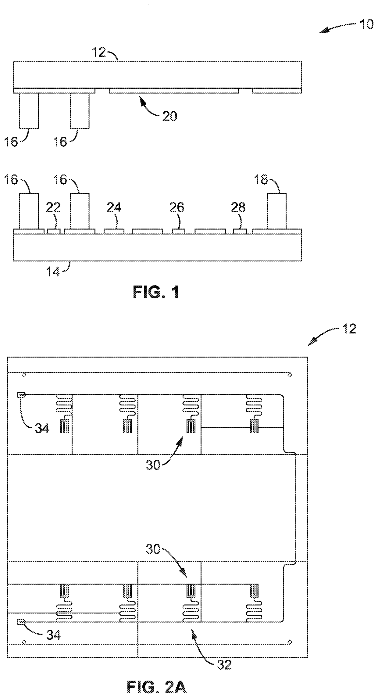
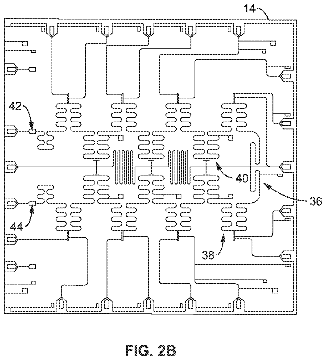
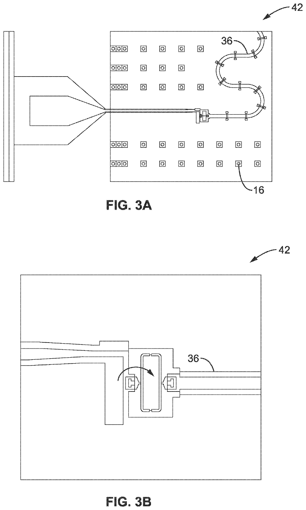
[0030]Referring more specifically to the drawings, for illustrative purposes, a superconducting quantum processor unit architecture that includes no fewer than eight superconducting transmon qubits that are coupled to a common high-quality superconducting meander coplanar waveguide resonator (Bus) are generally shown. Several embodiments of the technology are described generally in FIG. 1 to FIG. 7 to illustrate the characteristics and functionality of the devices, systems, and methods. It will be appreciated that the methods may vary as to the specific steps and sequence and the systems and apparatus may vary as to structural details without departing from the basic concepts as disclosed herein. The method steps are merely exemplary of the order that these steps may occur. The steps may occur in any order that is desired, such that it still performs the goals of the claimed technology.

[0031]Superconducting chip architectures with eight and sixteen qubits are used to generally illus...


PUM


Abstract

A superconducting quantum processor unit for quantum computing is provided. The processor unit is formed from the union of a qubit chip and a wiring chip with superconducting bonding bumps and spacers. The bumps may be densely distributed around active elements between the two chips and effectively form a Faraday-Cage around the qubits, control signal waveguides etc. The qubit chip has strategically spaced qubits and an inductively coupled probe line and the wiring chip has a bus coupling resonator with a number of voltage nodes and anti-nodes, a resonator pump and at least one SQUID. Magnetic flux applied through the SQUIDs changes their impedances and modifies the microwave boundary conditions of the bus. This allows in-situ shifting of electric field distributions of the resonance modes of the bus along the length of the bus. This tunes the coupling rates of the bus to all qubits simultaneously.

Description

CROSS-REFERENCE TO RELATED APPLICATIONS[0001]This application claims priority to, and the benefit of, U.S. provisional patent application Ser. No. 63 / 109,516 filed on Nov. 4, 2020, incorporated herein by reference in its entirety.STATEMENT REGARDING FEDERALLY SPONSORED RESEARCH OR DEVELOPMENT[0002]This invention was made with government support under Grant Number DE-AC02-05CH11231, awarded by the U.S. Department of Energy. The government has certain rights in the invention.NOTICE OF MATERIAL SUBJECT TO COPYRIGHT PROTECTION[0003]A portion of the material in this patent document is subject to copyright protection under the copyright laws of the United States and of other countries. The owner of the copyright rights has no objection to the facsimile reproduction by anyone of the patent document or the patent disclosure, as it appears in the United States Patent and Trademark Office publicly available file or records, but otherwise reserves all copyright rights whatsoever. The copyright...

Claims


Application Information

Patent Timeline
Patent Type & Authority Applications(United States)
IPC IPC(8): G06N10/40G01R33/035
CPCG06N10/40G01R33/0358G01R33/0354G06N10/20
Inventor SIDDIQI, IRFANLUO, JIEMARINELLI, BRIAN
Owner RGT UNIV OF CALIFORNIA
Learn More