
Fast-response direct-current current transformer based on multi-sensor fusion

a multi-sensor, fast-response technology, applied in the direction of instruments, measurement devices, measurement using dc-ac conversion, etc., can solve the problems of low measurement accuracy, considerable temperature drift, and the requirement of highly precise, fast and stable measurement of 10 ppm level of dc heavy current may not be satisfied, so as to reduce the possibility of dcct failure, reduce the time for dcct, and strong dynamic response capability

Active Publication Date: 2022-04-28
HUAZHONG UNIV OF SCI & TECH
View PDF0 Cites 6 Cited by
  • Summary
  • Abstract
  • Description
  • Claims
  • Application Information

AI Technical Summary

Benefits of technology

The patent text describes a new design for a DCCT based on multi-sensor fusion. This design aims to improve the dynamic response capability of the DCCT without affecting its steady-state performance such as measurement accuracy, stability, and time drifting. The technical effect of this new design is that it can prevent false balance and automatically recover from it, as well as achieve precise measurement of a large-scale dynamic DC heavy current. This is achieved through the fusion of the magnetic modulator and Hall current sensors, which makes the DCCT a strong dynamic response capable of facing a wide range of current amplitude changes. The system is not required to be restarted or scanned for a long time, which greatly reduces the time for the DCCT to resume normal work and response. The current correction module provides a feed-forward function and adjusts a secondary feedback current instantly according to the magnitude of the primary current, which avoids saturation of the magnetic core and strengthens the mutual inductance capability of the magnetic core, making the system enter the zero magnetic flux state faster.

Problems solved by technology

Nevertheless, problems such as low measurement accuracy and considerable temperature drifting may occur in most of the heavy current sensors, and the requirements of highly precise, fast, and stable measurement of 10 ppm level of the DC heavy current may not be satisfied as a result.
Although at present, the DCCT industry is mature, but research and improvement of solutions to problems related to false balance and dynamic response performance are still important issues.
At this time, the sensor cannot work at all and cannot automatically exit from the abnormal state.
Such false balance greatly limits the application range of the DCCT.
This method is inefficient and may not be widely used.
Although the application of the secondary current scanning method is mature, two problems are still found with this method: (1) The current scanning process is slow.
Besides, the inductance of the secondary coil of a large-range DCCT is large, and the fast scanning speed means a large voltage power supply.
At this time, a large induced voltage may be generated and the equipment may be damaged.
(2) The dynamic response performance of the system is not improved.
Even if the system leaves the false balance state and the measured current experiences the same large-scale fluctuation again, the system will still enter the false balance and scanning is required to start again, which is inefficient.
Fast response is performed in the face of a wide range of current amplitude changes, which greatly reduces the possibility of failure of the DCCT due to the false balance problem caused by the saturation of the magnetic core.

Method used


Image

  • Fast-response direct-current current transformer based on multi-sensor fusion
  • Fast-response direct-current current transformer based on multi-sensor fusion
  • Fast-response direct-current current transformer based on multi-sensor fusion

Examples


Embodiment Construction

[0026]To better illustrate the goal, technical solutions, and advantages of the disclosure, the following embodiments accompanied with drawings are provided so that the disclosure are further described in detail. It should be understood that the specific embodiments described herein serve to explain the disclosure merely and are not used to limit the disclosure.

[0027]The disclosure provides a fast-response direct-current current transformer (DCCT) based on multi-sensor fusion capable of improving dynamic response of a DCCT without affecting steady-state performance such as measurement accuracy, stability, time drifting, and temperature drifting of the DCCT. In this way, a false balance state is prevented from occurring in a dynamic process of the DCCT, automatic recovery of the false balance state caused by live closing, overloading, etc. is achieved, and precise measurement of a dynamic DC heavy current is accomplished.

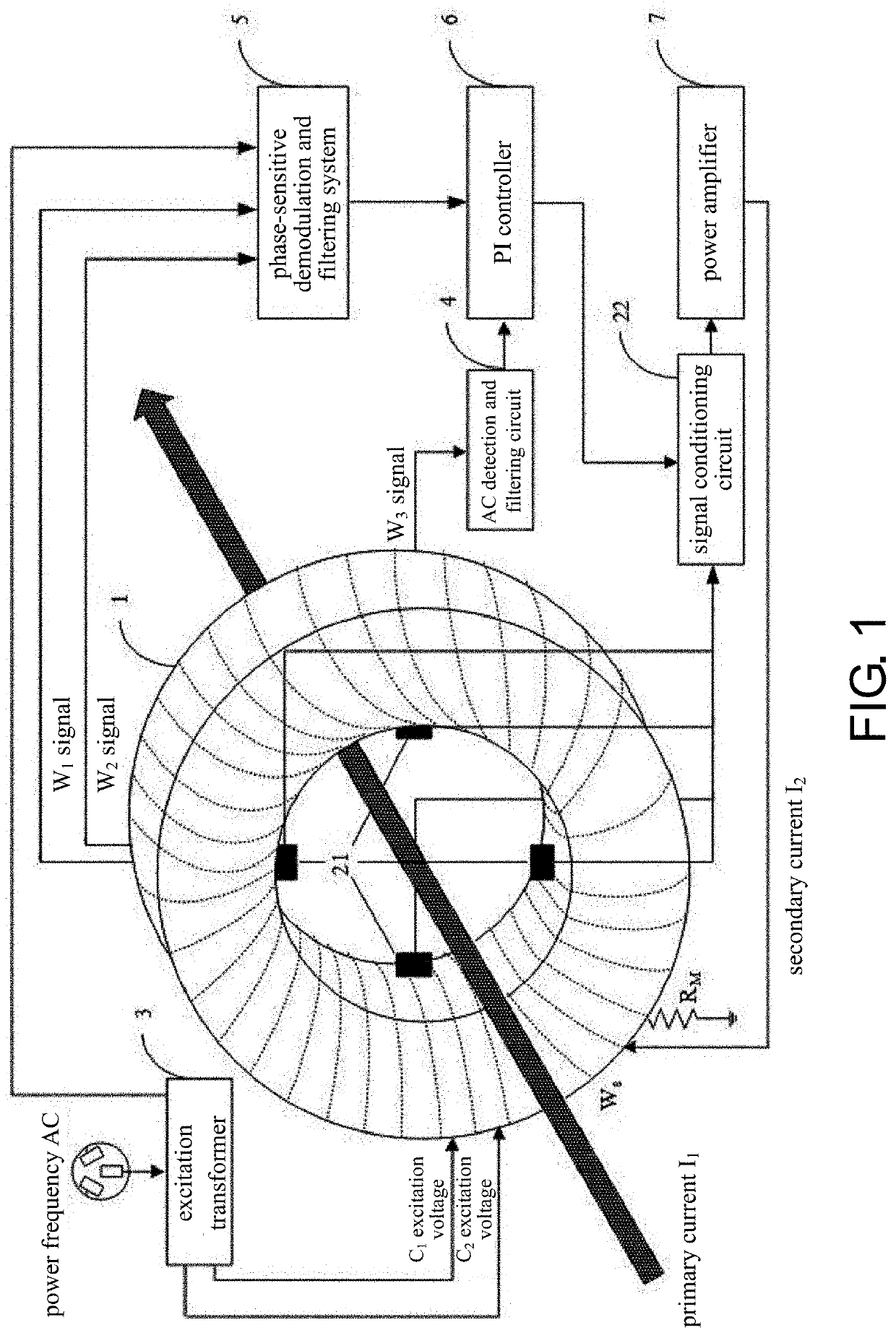
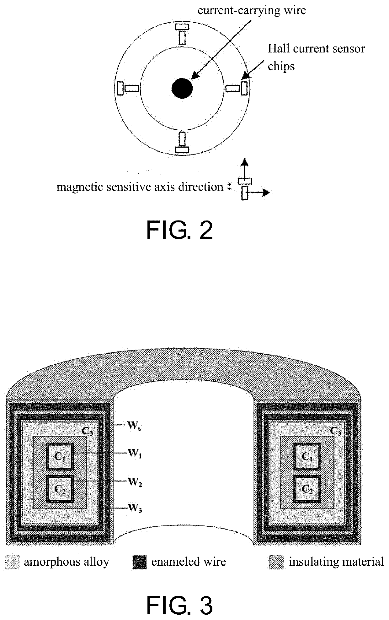
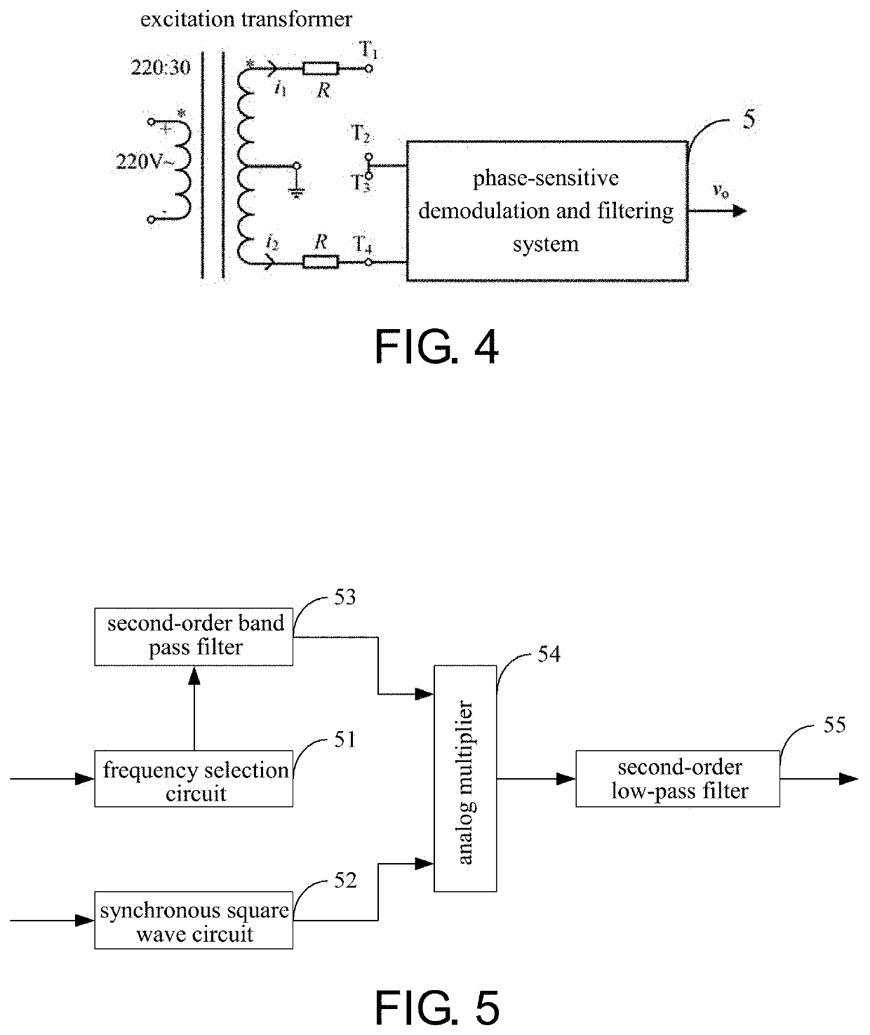
[0028]FIG. 1 illustrates a structure of a fast-response DCCT ba...


PUM


Abstract

A fast-response direct-current current transformer based on multi-sensor fusion is provided and includes: a magnetic modulator, a current correction module, an excitation transformer, an alternating current detection and filtering circuit, a phase-sensitive demodulation and filtering system, a PI controller, and a power amplifier. The current correction module measures a primary current and obtain a feed-forward signal, outputs a false balance state configured to control a magnetic core to quickly exit or avoid entering magnetic saturation after amplifying the feed-forward signal and a PI control signal, and keeps output of the magnetic modulator stable. The magnetic modulator and Hall current sensors are fused in the disclosure, such that the possibility of failure due to a false balance problem caused by saturation of a magnetic core is reduced. After the false balance is generated the magnetic core may be controlled to quickly exit a magnetic saturation state through a feed-forward output current.

Description

BACKGROUNDTechnical Field[0001]The disclosure relates to a technical field of current detection, and in particular, relates to a fast-response direct-current current transformer based on multi-sensor fusion.Description of Related Art[0002]Heavy current (specifically refers to a high-intensity current greater than or equal to 1 kA) is widely applied in various industries such as industrial production, direct current (DC) transmission, high-speed railways, and scientific experiments. As such, the techniques used for heavy current measurement have always been important research topics. At present, the methods commonly used for DC heavy current measurement include the use of a shunt, a DC transformer, a Rogowski coil sensor, an optical fiber sensor, and a Hall effect DC sensor and so on. Nevertheless, problems such as low measurement accuracy and considerable temperature drifting may occur in most of the heavy current sensors, and the requirements of highly precise, fast, and stable mea...

Claims


Application Information

Patent Timeline
IPC IPC(8): G01R15/20H03F3/21
CPCG01R15/202H03F3/21G01R19/0038G01R15/185G01R19/20
Inventor HAN, XIAOTAOZHANG, SHAOZHEWANG, YILINXIE, JIANFENG
Owner HUAZHONG UNIV OF SCI & TECH
Learn More