
Control device of gear transmission-equipped vehicle and method of controlling gear transmission-equipped vehicle

Active Publication Date: 2022-04-14
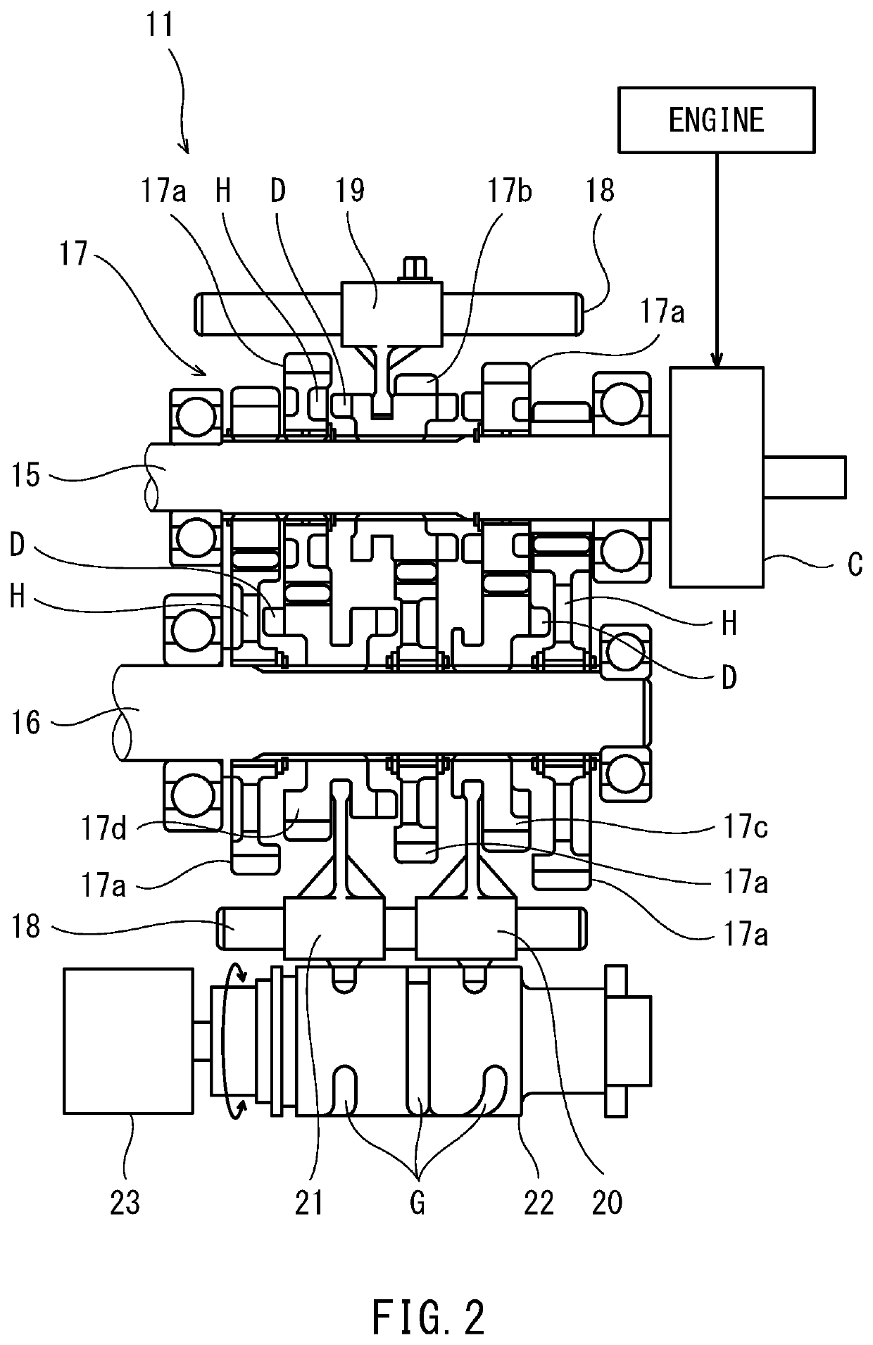
KAWASAKI MOTORS LTD
View PDF4 Cites 0 Cited by
  • Summary
  • Abstract
  • Description
  • Claims
  • Application Information

AI Technical Summary

Benefits of technology

The patent is about a control device for gear transmission vehicles. The device includes a condition determiner that checks if the vehicle is ready to start and a power controller that reduces the power sent to the gear transmission when the determiner determines that the vehicle is ready to start. The condition determiner looks for certain signs, like a specific gear position sensor reading and a specific speed difference, to confirm if the vehicle is ready to start. The technical effect of this device is to improve the control and efficiency of gear transmission vehicles.

Problems solved by technology

However, when the engagement of the gear selector with the gear is incomplete at the time of the completion of a speed change operation, the gear selector may be unintentionally disengaged from the gear although next speed change manipulation is not being performed (gear disengagement).
Therefore, when the gear selector is reengaged with the gear after being disengaged from the gear, shock is generated due to a speed difference between the gear and the gear selector.

Method used


Image

  • Control device of gear transmission-equipped vehicle and method of controlling gear transmission-equipped vehicle
  • Control device of gear transmission-equipped vehicle and method of controlling gear transmission-equipped vehicle
  • Control device of gear transmission-equipped vehicle and method of controlling gear transmission-equipped vehicle

Examples


embodiment 1

[0031]FIG. 4 is a block diagram showing the control device 12 and the like according to Embodiment 1. As shown in FIG. 4, the control device 12 includes a condition determiner 31 and an engine controller 32 (power controller) in terms of functions. The control device 12 includes a processor, a memory, an I / O interface, and the like in terms of hardware. The memory includes a storage (a hard disk, a flash memory, etc.) and a main memory (RAM). Each of the condition determiner 31 and the engine controller 32 is realized in such a manner that the processor utilizes the main memory to perform calculation processing based on a program stored in the storage.

[0032]The gear position sensor 23, an engine rotational frequency sensor 24, a rear wheel vehicle speed sensor 25, a throttle opening degree sensor 26, a clutch switch 27, and the like are electrically connected to an input side of the control device 12. A throttle device 41, an ignition device 42, a fuel supply device 43, and the like...

embodiment 2

[0053]FIG. 7 is a block diagram showing a control device 112 and the like according to Embodiment 2. The same reference signs are used for the same components as Embodiment 1, and the repetition of the same explanation is avoided. As shown in FIG. 7, the control device 112 includes the condition determiner 31 and a clutch controller 132 (power controller). A clutch actuator 150 is electrically connected to an output side of the control device 112. The clutch actuator 150 operates the main clutch C (see FIG. 2).

[0054]When the condition determiner 31 determines that the start condition of the power reduction control is satisfied, the clutch controller 132 controls the clutch actuator 150 such that the power transmitting ratio of the main clutch C decreases. To be specific, as the power reduction control, the clutch controller 132 controls the clutch actuator 150 such that the main clutch C changes from a completely engaged state to a half-engaged state. With this, the power reduction ...


PUM


Abstract

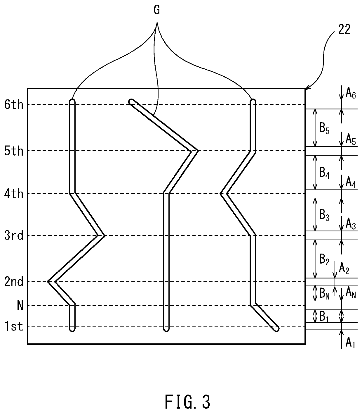
A control device of a gear transmission-equipped vehicle includes a power controller that starts power reduction control when it is determined that a start condition is satisfied, the power reduction control being control of reducing power transmitted from a driving source to a gear transmission. The start condition includes: a condition that a detection value of a gear position sensor that detects a current gear position of the gear transmission falls within a transition region between engagement regions corresponding to respective gear positions; and a condition that a speed difference obtained by subtracting a rotational speed of an output shaft of the gear transmission from a rotational speed of an input shaft of the gear transmission is a threshold or more.

Description

CROSS-REFERENCE TO RELATED APPLICATION[0001]The present application claims priority to Japanese Patent Application No. 2020-171785, filed on Oct. 12, 2020, the entire disclosure of which is incorporated herein by reference.BACKGROUND OF THE INVENTIONTechnical Field[0002]The present disclosure relates to a control device of a gear transmission-equipped vehicle.Description of the Related Art[0003]An engine vehicle including a gear transmission is known (see Japanese Laid-Open Patent Application Publication No. 2019-85894, for example). In a gear transmission, when a shift drum rotates, and a shift fork slides a gear selector, the gear selector is engaged with a gear, and a speed change path of a desired change gear ratio becomes a power transmitting state.[0004]However, when the engagement of the gear selector with the gear is incomplete at the time of the completion of a speed change operation, the gear selector may be unintentionally disengaged from the gear although next speed chan...

Claims


Application Information

Patent Timeline
IPC IPC(8): B62M11/06F16H61/688F16H3/00F16H63/18B62M25/08
CPCB62M11/06F16H61/688B62M25/08F16H63/18F16H3/006B62M2025/006B62M25/06B62J45/41F16H59/46F16H2059/6807F16H61/0437F16H63/46F16H59/44F16H59/42F16H63/502F16H2061/0477F16H3/089F16H2200/0047B60Y2200/12F16H61/66272
Inventor UEDA, KENGOWATANABE, HIROYUKIARIMA, KAZUKI
Owner KAWASAKI MOTORS LTD
Learn More