
Power transmission structure of scooter

Inactive Publication Date: 2011-05-26
SUNPEX TECH
View PDF9 Cites 1 Cited by
  • Summary
  • Abstract
  • Description
  • Claims
  • Application Information

AI Technical Summary

Benefits of technology

[0010]The main object of the power transmission structure of this invention is to improve the shortcomings of conventional scooter such as bulky volume, high cost and strenuous effort in driving etc. by providing a power source on one of rear wheels to drive scooter.
[0012]A power transmission structure of scooter, in which one of rear wheels of the scooter is provided with a power source and the other rear wheel is a free wheel. By the usage of power equipment for driving a single rear wheel, the volume taken by the power equipment is reduced and more space is thus available for accommodation of more power equipments such that both the running distance and running time can be lengthened. As there is no such elongated structure of transmission therein, the power transmission structure of scooter has the advantages of having sufficient power and power-saving effect so as to achieve cost-saving.

Problems solved by technology

Hence, driving effect of a single power source is bad and insufficient horsepower phenomena often occur.
Thus, it is unsafe in driving; even it is easy to have traffic accident.
This results in defects of bulky volume and high cost.
In addition, the motor suffers horsepower loss through power transmission and mechanical loss through the transmission shaft etc . . . . Therefore, there are defects of horsepower insufficiency, strenuous effort in driving or cost-up due to the need of more horsepower in the above patent.

Method used


Image

  • Power transmission structure of scooter
  • Power transmission structure of scooter
  • Power transmission structure of scooter

Examples


Embodiment Construction

[0017]The objects, the technical contents and the expected effect of the present invention will become more apparent from the detailed description of the preferred embodiments in conjunction with the accompanying drawings.

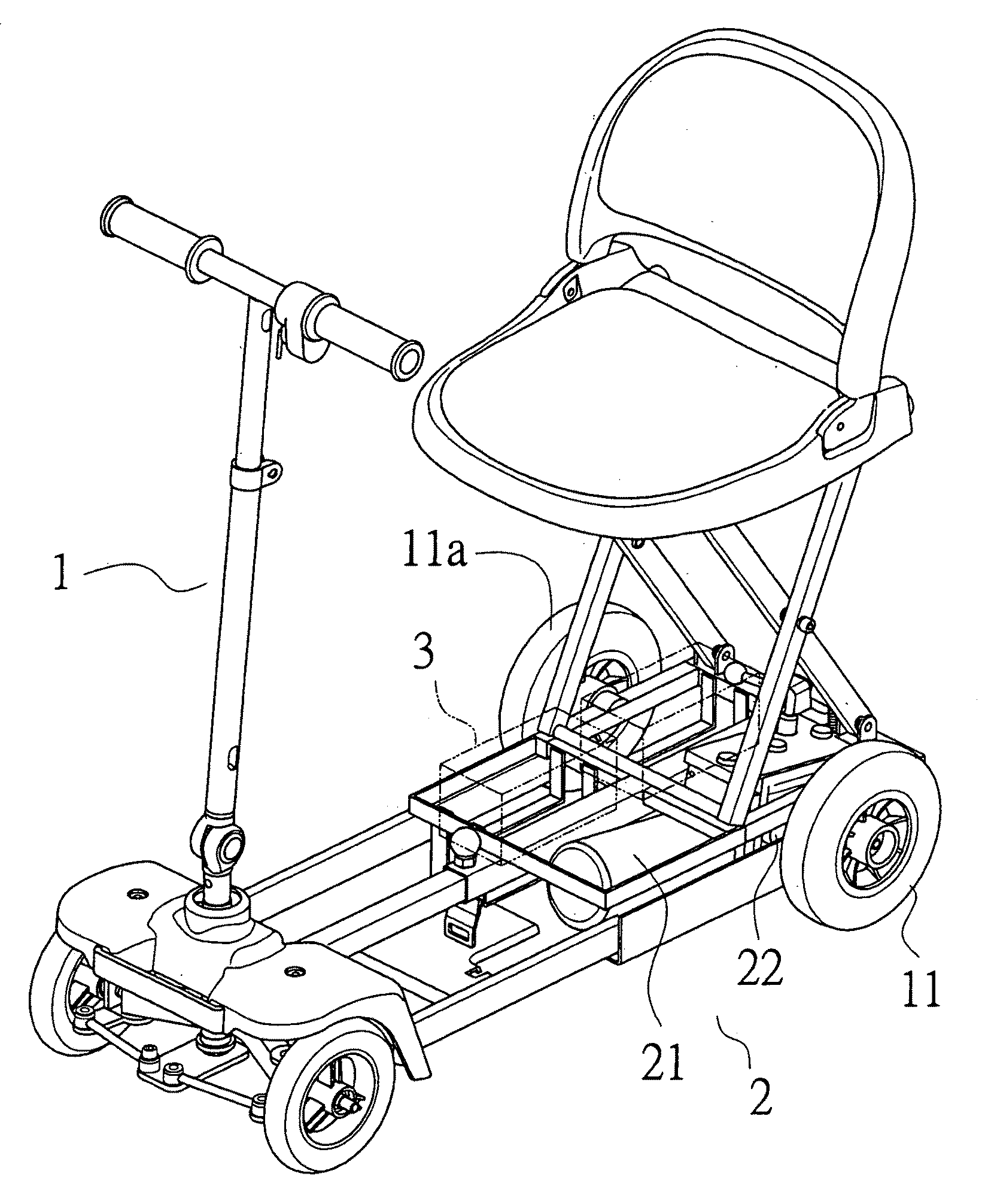
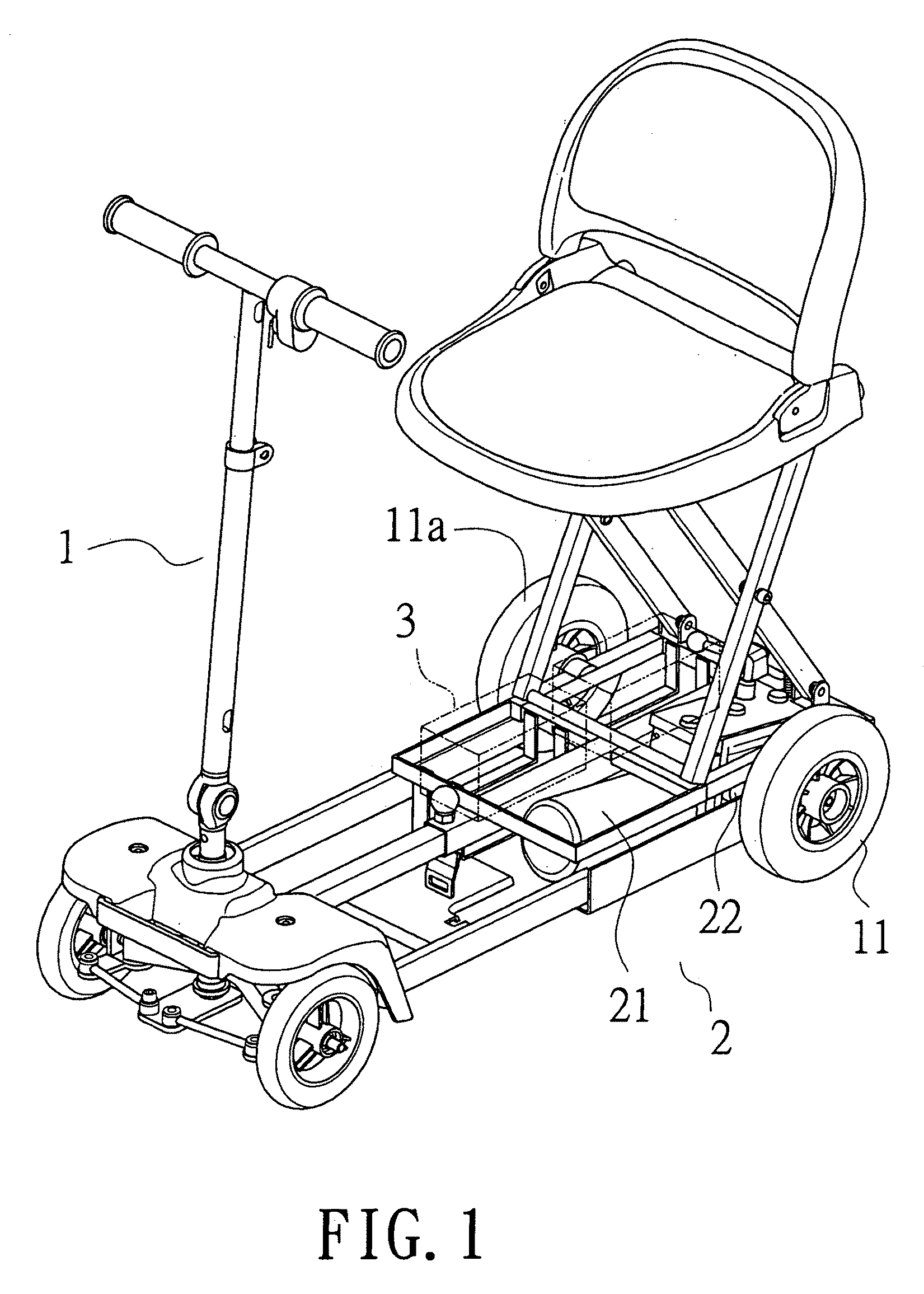
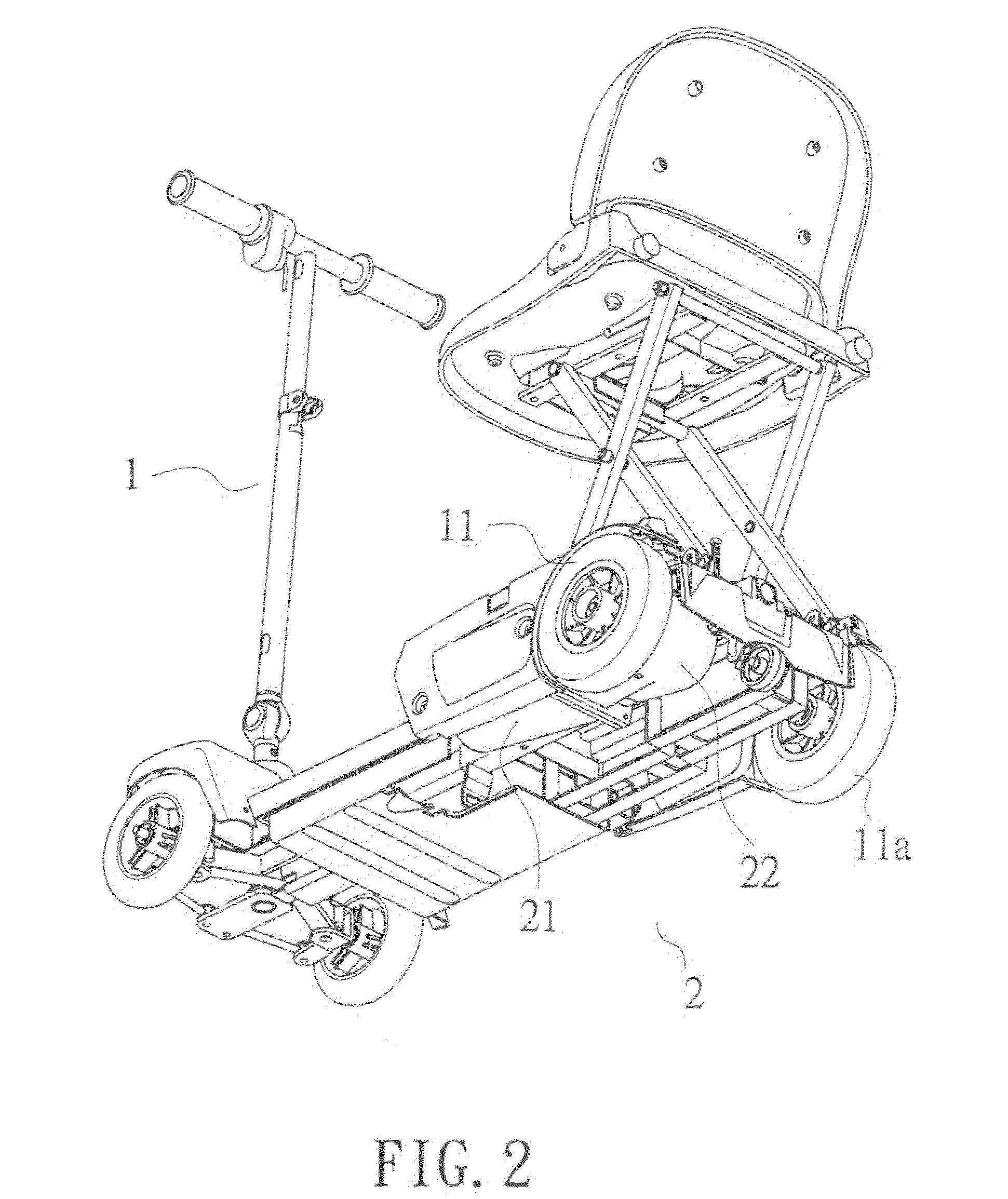
[0018]FIGS. 1 to 4 are perspective exploded view, whole outline view of structure, top view and side schematic view respectively showing the power transmission structure of scooter of the present invention, in which scooter (1) is driven by a power mechanism (2), wherein:

[0019]one rear wheel (11) of the scooter (1) is provided with a transmission shaft (12) coupled with the power mechanism (2) and the other rear wheel (11a) is a free wheel. In the power mechanism (2), a power source (21) is used to drive a reducer (22) so as, in turn, to drive the scooter (1).

[0020]By providing the power mechanism (2) for driving a single rear wheel, the volume taken by the power equipment is reduced and more space is thus available for accommodation of more batteries (3) such that...


PUM


Abstract

This invention relates to a power transmission structure of scooter, in which one rear wheel of the scooter is provided with a power source and the other rear wheel is a free wheel. By the usage of power equipment for driving a single rear wheel, the volume taken by the power equipment is reduced and more space is thus available for accommodation of more power equipments such that both the running distance and running time can be lengthened. As there is no such elongated structure of transmission therein, the power transmission structure has advantages of having sufficient power and power-saving effect so as to achieve cost-saving.

Description

BACKGROUND OF THE INVENTION[0001]1. Field of the Invention[0002]The present invention relates to a power transmission structure of scooter, more particularly to a power transmission structure enabling to increase running distance and running time of scooter, which is driven by a power source provided on one of rear wheels so as to improve conventional defects happened in prior art.[0003]2. Brief Description of the Prior Art[0004]Usually, power source of a conventional scooter is provided on rear wheel side and a single power source is utilized to drive two rear wheels which in turn move front wheels so as to move the scooter.[0005]An electric scooter disclosed in Taiwanese Patent Gazette No. M269882 comprises a front wheel set and a rear wheel set spaced with each other, a set of frame coupling the front wheel set and the rear wheel set, a stem unit and a control unit provided at front side of the frame, a seat provided at rear side of the frame, and a power unit assembled on the fr...

Claims


Application Information

Patent Timeline
IPC IPC(8): B60K7/00
CPCB60Y2200/84B62K2204/00B62K3/002
Inventor LIN, YONG-SIANG
Owner SUNPEX TECH
Learn More