
Surgical Implant For Repairing A Defect In Spinal Dura Mater

a surgical implant and dura mater technology, applied in the field of surgical implants, can solve the problems of intracranial hypotension, low volume of csf around the brain and spinal cord, patient may have very limited ability to function, and may be injured due to nerve decompression instruments,

Pending Publication Date: 2022-04-14
JENKINS NEUROSPINE LLC
View PDF0 Cites 0 Cited by
  • Summary
  • Abstract
  • Description
  • Claims
  • Application Information

AI Technical Summary

Benefits of technology

This patent aims to create a surgical implant that can be used to repair defects in biological structures, such as the dural sac and blood vessels, by providing a seal to prevent leakage and promote better healing. The implant has two layers - an inner layer that protects nerves and prevents platelet aggregation, and an outer layer that can be extended to cover the defect. It can be inserted through the defect in a retracted position and then extended to its full length to seal it. This invention provides a better solution for repairing biological defects without compromising the patient's outcomes.

Problems solved by technology

This results in intracranial hypotension, a low volume of CSF remaining around the brain and spinal cord.
Often, a patient may have very limited ability to function while in the upright position.
During spine surgery, injury may occur due to instruments used to decompress nerves, misplaced implants or grafts, manipulation, and ischemia (compromised blood supply).
The risk of having a spinal cord injury or a dural tear during spine surgery increases with age as the surgeon needs to cut through toughened spinal ligaments, and in the process, damage the dura.
Surgery to the back of the spine has a higher risk of spinal cord injury or dural tears since it requires cutting through spinal ligaments, which may injure the dura or cord.
A disadvantage of the methods currently used in clinical practice is that they only allow for the dural patches either to be laid on top of the tear, or sewn into the defect as a single layer, thus creating either minimal seal, or an opportunity for an uneven seal, or an initial seal that becomes leaky when the contents develop higher pressure including leaking at the suture line or suture holes because there are no additional layers to block leakage from the repair site.
A further disadvantage of such implants is they may lead to tissue damage below the dura mater occurring as a result of the suturing process.

Method used


Image

  • Surgical Implant For Repairing A Defect In Spinal Dura Mater
  • Surgical Implant For Repairing A Defect In Spinal Dura Mater
  • Surgical Implant For Repairing A Defect In Spinal Dura Mater

Examples


Embodiment Construction

[0053]The present teachings are described more fully hereinafter with reference to the accompanying drawings. The following description is presented for illustrative purposes only and the present teachings should not be limited to these embodiments.

[0054]In compliance with the statute, the present teachings have been described in language more or less specific as to structural and methodical features. It is to be understood, however, that the present teachings are not limited to the specific features shown and described, since the systems and methods herein disclosed comprise preferred forms of putting the present teachings into effect.

[0055]For purposes of explanation and not limitation, specific details are set forth such as particular architectures, interfaces, techniques, etc. in order to provide a thorough understanding. In other instances, detailed descriptions of well-known devices, circuits, and methods are omitted so as not to obscure the description with unnecessary detail...


PUM

PropertyMeasurementUnit
Flexibilityaaaaaaaaaa
Areaaaaaaaaaaa
Tensionaaaaaaaaaa

Abstract

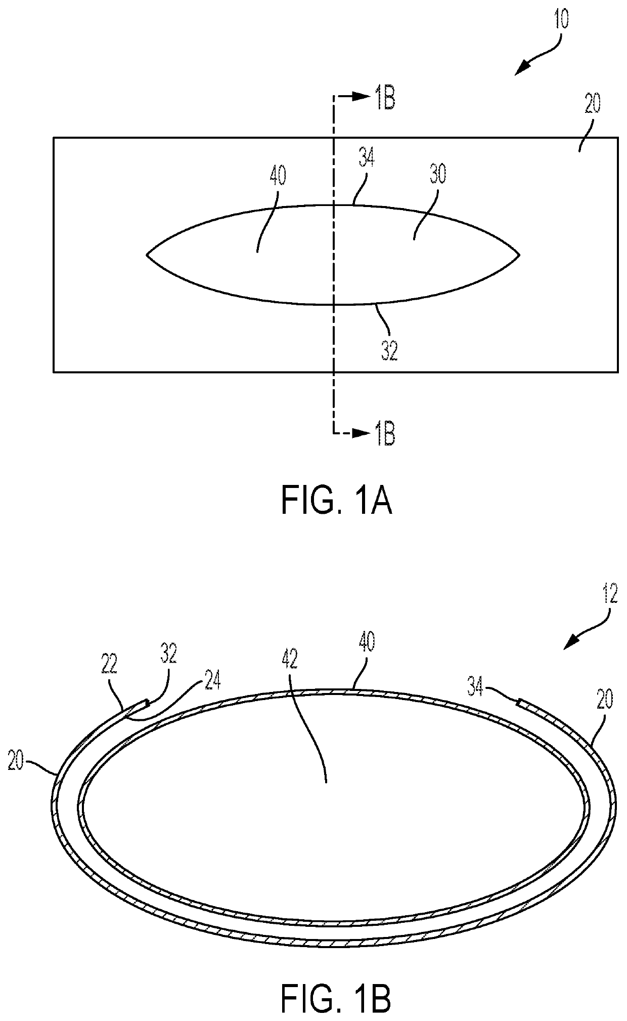
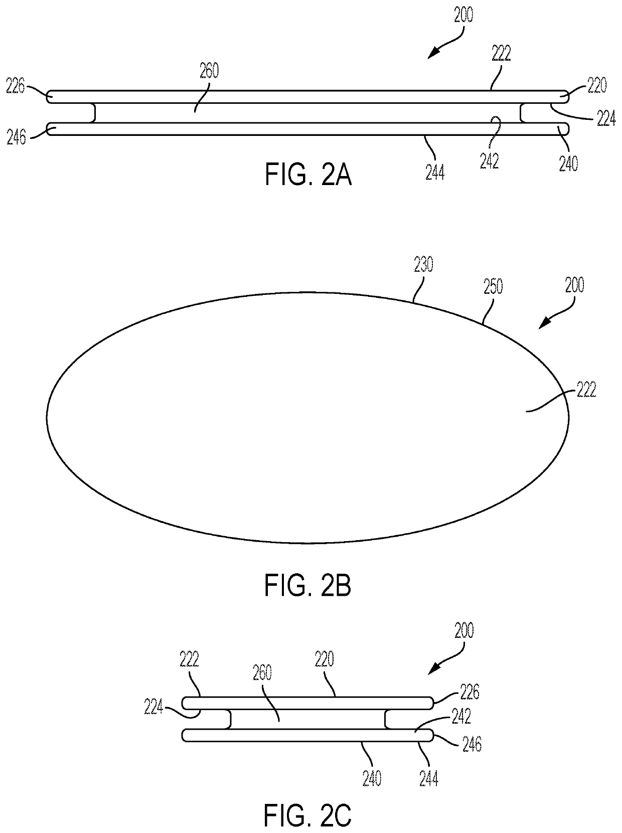
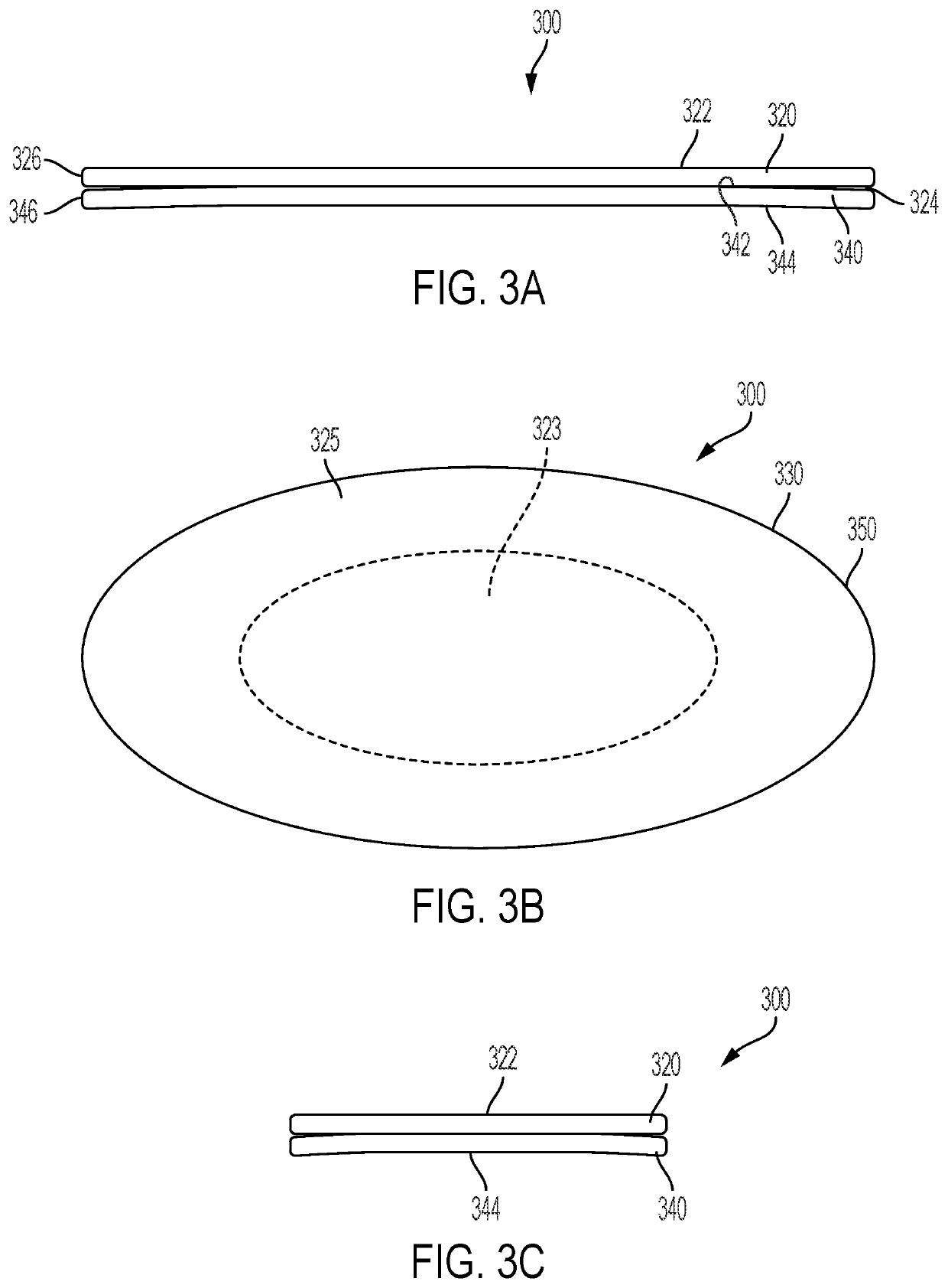
A surgical implant for repairing a defect. The implant has a first layer and a second layer. Each layer is flexible and planar. The first layer has an inner portion remote from a periphery, and an outer portion between the periphery and the inner portion. The second layer has an inner portion remote from a periphery, and an outer portion between the periphery and the inner portion. A bottom surface of the first layer near the inner portion thereof is connected to top surface of the second layer near the inner portion thereof so that the inner portion of the top layer is fixed relative to the inner portion of the second layer and the outer portion of the first layer is moveable relative to the outer portion of the second layer.

Description

TECHNICAL FIELD[0001]The present disclosure generally relates to a surgical implant. More specifically, the present disclosure relates to a surgical implant for repairing a defect in a spinal dura mater.BACKGROUND[0002]The brain and spinal cord are bathed in fluid known as cerebrospinal fluid (CSF). This fluid is held inside layers of connective tissue called the meninges, which surround the brain and spinal cord. There are three meningeal layers: the pia mater; the arachnoid mater; and the dura mater. The dura mater, sometimes called the dura, is the outermost layer of the meninges. The dura is normally a tough connective tissue. The CSF is contained within the subarachnoid space, between the arachnoid mater and the pia mater layers. A spinal CSF leak happens when the spinal dura mater has a hole or tear, allowing CSF to leak out of this enclosed space. This results in intracranial hypotension, a low volume of CSF remaining around the brain and spinal cord. The loss of volume of CS...

Claims


Application Information

Patent Timeline
IPC IPC(8): A61F2/00A61L27/24
CPCA61F2/0063A61L27/24A61F2230/0008A61L2430/32A61F2230/0039A61B17/0057A61B2017/00597A61B2017/00606
Inventor JENKINS, III, ARTHUR L.
Owner JENKINS NEUROSPINE LLC
Learn More