Device for wavefront analysis and microscopic imaging systems comprising such analysis devices

a wavefront analysis and microscopic imaging technology, applied in the direction of optical radiation measurement, fluorescence/phosphorescence, instruments, etc., can solve the problems of convergence reliability, difficult implementation of direct measurement of optical defects, and complex implementation of approaches in microscopic imaging, so as to improve the intercorrelation between images

Pending Publication Date: 2022-03-31
IMAGINE OPTIC
View PDF9 Cites 0 Cited by
  • Summary
  • Abstract
  • Description
  • Claims
  • Application Information

AI Technical Summary

Benefits of technology

[0024]The applicants have shown that the wavefront analysis device described thus would enable, compared to the known devices of the prior art, a significant improvement in the precision of the analysis, whilst avoiding the generation of a guide star. Indeed, the field diaphragm arranged thus in the wavefront analysis device allows the size of the image formed by each microlens on the detection plane to be controlled and allows the overlap between two images formed by two adjacent microlenses to be limited, yet without limiting the size of the field-of-view imaged by the microscopic imaging system to which said wavefront analysis device is connected.
[0081]This implementation is made possible, for example, by introducing two types of fluorescent elements into the object, and prevents the use of photons of the emission fluorescent light intended to form the image of the object for analyzing the wavefront, which is particularly critical in the case of weakly fluorescent objects, as is generally the case for biological objects.

Problems solved by technology

However, it is based on an overall optimization that requires the use of iterative algorithms, the convergence reliability, the execution speed and the calibration of which are limiting, particularly in the case of dynamic imaging objects.
However, the direct measurement of optical defects approach remains difficult to implement.
These approaches require complex implementation in microscopic imaging, whether this is in terms of the preparation of the object of interest or of the instrumental design.
However, the majority of biological objects of interest in high-resolution microscopy are made up of multiple microscopic structures corresponding to significant phase fluctuations: the isoplanetic patch is generally limited to one hundred square microns, which represents a significant limitation for the spatio-temporal high-resolution study of large structures, such as, for example, the study of neural networks in the field of neuroimaging.
However, the applicant has revealed limitations in the previously described method.
Indeed, in practice, overlaps are found between the images formed by the microlenses, with these overlaps being able to induce errors in the intercorrelation computations and inaccuracies in the analysis of the wavefront.
Furthermore, the described method only allows an analysis of the average wavefront to be carried out on a given field-of-view, without taking into account the isoplanetic patch of the object.

Method used


Image

  • Device for wavefront analysis and microscopic imaging systems comprising such analysis devices
  • Device for wavefront analysis and microscopic imaging systems comprising such analysis devices
  • Device for wavefront analysis and microscopic imaging systems comprising such analysis devices

Examples


Embodiment Construction

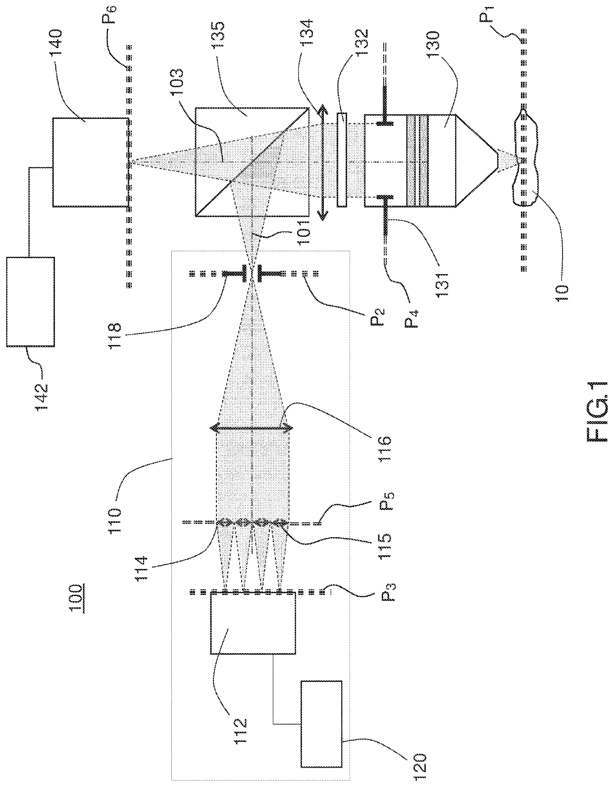
[0098]FIG. 1 schematically illustrates an example of a wavefront analysis device 110 according to the present description, connected to a fluorescence microscopic imaging system 100 with optical sectioning.

[0099]The fluorescence microscopic imaging system 100 with optical sectioning comprises an illumination path (not shown in FIG. 1) for illuminating an optical section of a volumetric and fluorescent object 10.

[0100]The microscopic imaging system 100 also comprises an imaging path 103 and an analysis path 101 comprising the wavefront analysis device 110.

[0101]The imaging path 103 comprises, in the example of FIG. 1, a microscope objective lens 130 comprising a pupil 131 in a pupil plane P4, a focusing optic 134, a fluorescence filter 132, an imaging detector 140 comprising a detection plane P6, a processing unit 142 for processing signals acquired by the detector 140.

[0102]Depending on the type of microscopic imaging system (for example, light-sheet or multiphoton), the imaging det...


PUM

PropertyMeasurementUnit
sizeaaaaaaaaaa
sizeaaaaaaaaaa
focal distanceaaaaaaaaaa

Abstract

A device for analysing a wavefront may be connected to a fluorescence microscopy imaging system with optical sectioning, equipped with a microscope objective including a pupil in a pupil plane, the analysis device including a two-dimensional detector including a detection plane; a two-dimensional arrangement of microlenses, arranged in an analysis plane, each microlens forming, on the detection plane, when the analysis device is connected to the microscopic imaging system, an image of an object situated in a focal plane of the microscope objective, with a given analysis field; an optical relay system optically conjugating the analysis plane and the pupil plane; a field diaphragm positioned in a plane optically conjugated with the plane of detection, and defining said analysis field; a processing unit that determines, based on the set of images formed by the microlenses, a two-dimensional map of a characteristic parameter of the wavefront in said analysis plane.

Description

[0001]The present invention contains a description and a set of claims. It also contains figures, an abstract and a figure for the abstract.TECHNICAL FIELD OF THE INVENTION[0002]The present description relates to wavefront analysis devices, microscopic imaging systems comprising such analysis devices and microscopic imaging methods using such analysis devices. The present description more specifically relates to systems and methods for fluorescence microscopic imaging with optional sectioning, for example, light-sheet or multiphoton systems and methods for fluorescence microscopic imaging.PRIOR ART[0003]In microscopy, in particular high-resolution imaging, the quality of the image in terms of resolution and of contrast is directly associated with the incident wavefront on the imaging detector, for example, a camera. The wavefront, i.e. the surface of equal phase of a wave, is, in a microscopic imaging system, disrupted both by the optical defects introduced by the optical elements o...

Claims


Application Information

Patent Timeline
Patent Type & Authority Applications(United States)
IPC IPC(8): G01N21/64G02B21/16G02B21/36G02B21/06H04N5/225
CPCG01N21/6458G02B21/16G01N2201/06113G02B21/06H04N5/2256G02B21/365G01J9/00G01J2009/002G01J3/4406G02B21/0076H04N23/56
Inventor HARMS, FABRICELEVECQ, XAVIER
Owner IMAGINE OPTIC
Why Eureka
Try Eureka