Drug reservoir for separate storage of substances

a technology for storing substances and drug reservoirs, applied in the field of medical use, can solve the problems of affecting the safety of patients, so as to reduce or eliminate at least one drawback

Pending Publication Date: 2022-03-17
NOVO NORDISK AS
View PDF0 Cites 0 Cited by
  • Summary
  • Abstract
  • Description
  • Claims
  • Application Information

AI Technical Summary

Benefits of technology

[0010]It is an object of the invention to eliminate or reduce at least one drawback of the prior art, or to provide a useful alternative to prior art solutions.
[0018]The non-liquid-bound gas is present as a gas volume between a surface portion of the proximal liquid volume and a surface portion of the proximal chamber, or as a gas bubble in the proximal liquid volume. Being non-liquid-bound the proximal gas volume provides resilience to the proximal chamber, in the sense that the second contents becomes compressible, as opposed to if the second contents consisted of liquid only. This has the effect that the two pistons will be broken loose sequentially instead of simultaneously. When a force of sufficient magnitude is applied to the rear piston the rear piston will be able to break loose from the inner wall of the reservoir body, whereby the force resisting movement of the rear piston will shift from a static friction force to a, lower, kinetic friction force, before the applied force is transferred to the front piston via the second contents. The break loose force needed to mobilise the two pistons is thus lower than if the second contents are incompressible and two static friction forces must be overcome at the same time.
[0019]As a consequence, when used in a drug delivery device the drug reservoir provides for a lower activation force during a drug expelling operation. For automatic injection devices, for example, this means that a less powerful spring may be employed to drive the drug expelling mechanism. A less powerful spring will in a pre-loaded state strain the interfacing device components less, reducing the risk of creep or breakage and / or allowing for use of less deformation resistant materials and / or or configurations, thereby reducing the cost of the drug delivery device.
[0038]The first sub-atmospheric pressure environment ensures that a negative pressure is established in the front chamber which will pull the first piston towards the free surface of the first liquid volume, minimising a present front chamber gas volume.
[0039]The second sub-atmospheric pressure environment may be established in a surrounding gas selected by the manufacturer in accordance with the constitution of the second liquid volume, e.g. air or an inert gas. The latter may be chosen to minimise the risk of undesired chemical reactions with the second liquid volume.

Problems solved by technology

Subcutaneous drug delivery is often associated with discomfort as many people dislike the thought of having an injection needle inserted through the skin.
A common drawback of such devices is the fact that during storage, over time, the piston material tends to adhere to the reservoir material, which means that a significant static friction must be overcome in order to initiate a drug mixing and / or expelling.
In case of a manually driven piston rod the sudden shift from static to kinetic friction as the pistons break loose is likely to cause a jerking forward motion of the pistons as the user tries to compensate for the sudden acceleration by significantly decreasing the force input.
Apart from being an unpleasant user experience it may in fact lead to an overly fast transfer of the rear chamber liquid to the front chamber.
If the front chamber carries a dry powder to be reconstituted the transfer process may even lead to undesired foaming.
A downside of this is that once the friction becomes kinetic the power available for the actual drug expelling is very high and may lead to an unpleasantly high speed of delivery.
Adding to that, a powerful spring requires stronger interfacing injection device parts to avoid creep or breakage during a potential medium- or long-term storage period in pre-loaded state, increasing both the cost and the weight of the injection device.

Method used


Image

  • Drug reservoir for separate storage of substances
  • Drug reservoir for separate storage of substances
  • Drug reservoir for separate storage of substances

Examples


Embodiment Construction

[0058]When / If relative expressions, such as “upper” and “lower”, “left” and “right”, “horizontal” and “vertical”, “clockwise” and “counter-clockwise”, etc., are used in the following, these refer to the appended figures and not necessarily to an actual situation of use. The shown figures are schematic representations for which reason the configuration of the different structures as well as their relative dimensions are intended to serve illustrative purposes only.

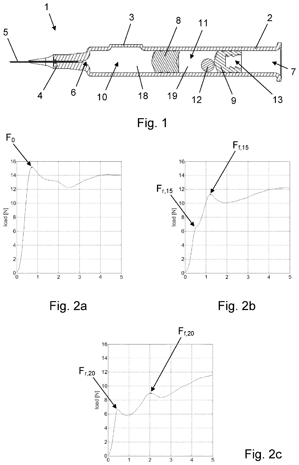
[0059]FIG. 1 is a longitudinal section view of a drug reservoir 1 according to an exemplary embodiment of the invention. The drug reservoir 1 is depicted in a pre-use state, i.e. in a state as supplied by the manufacturer (albeit without a rigid needle protector).

[0060]The drug reservoir 1 has a generally cylindrical reservoir body 2 with a bypass channel 3 and a narrowed distal end portion 4. An injection needle 5 is fixed to the distal end portion 4 and establishes fluid communication to a reservoir outlet 6. A front pist...


PUM


Abstract

The present invention provides a drug reservoir (1) comprising a reservoir body (2) extending between an outlet end (4) and a proximal end (7), a front piston (8) arranged in a pre-use position within the reservoir body (2) between the outlet end (4) and the proximal end (7), a rear piston (9) arranged within the reservoir body (2) between the front piston (8) and the proximal end (7) a distal chamber (10) defined by the outlet end (4), a first portion of the reservoir body (2), and the front piston (8), the distal chamber (10) holding first contents (18), a proximal chamber (11) defined by the front piston (8), a second portion of the reservoir body (2), and the rear piston (9), the proximal chamber (11) holding second contents (12, 19) comprising a proximal liquid volume (19), and bypass means (3) allowing fluid flow past the front piston (8) in an advanced position of the front piston (8) in the reservoir body (2), wherein the second contents (12, 19) further comprises a proximal gas volume (12) lying within a volume range having a predetermined minimum value.

Description

FIELD OF THE INVENTION[0001]The present invention relates to reservoirs for medical use and particularly to reservoirs having more than one chamber.BACKGROUND OF THE INVENTION[0002]Within some medical treatment areas a combination therapy involving co-administration of at least two drugs is advantageous because of synergistic or additive effects. For example, within diabetes care, in the management of type 2 diabetes mellitus, concomitant use of certain insulin and glp-1 products has been shown to reduce HbA1c levels in subjects, thereby improving glycaemic control.[0003]Many drugs must be administered parenterally to be effective in the body and some of these, e.g. insulin and glp-1, may require one or more doses to be delivered subcutaneously on a daily basis. Subcutaneous drug delivery is often associated with discomfort as many people dislike the thought of having an injection needle inserted through the skin. An undisclosed number of people even suffer from needle-phobia, and t...

Claims


Application Information

Patent Timeline
Patent Type & Authority Applications(United States)
IPC IPC(8): A61M5/20A61M5/19A61M5/31
CPCA61M5/2066A61M5/19A61M2005/3114A61M2005/3132A61M2207/00A61M5/2033A61M5/2448
Inventor WINTHER, KNUD SKIFTER
Owner NOVO NORDISK AS
Why Eureka
Try Eureka