Stackable Fuel Cell

a fuel cell and stack technology, applied in the field of stackable fuel cells, can solve the problems of less practical stacks for applications where portability is desired, more fuel cell units, and uneven distribution of reacting fluids (fuel, reactant, or both) throughout the volume of stacks, and achieves easy transportability, high output power, and low weight

Active Publication Date: 2022-03-03
GHOSH CHUNI LAL
View PDF0 Cites 0 Cited by
  • Summary
  • Abstract
  • Description
  • Claims
  • Application Information

AI Technical Summary

Benefits of technology

The invention is a flexible PEM fuel cell structure that is constructed of layers of flexible materials aligned parallel along their broadside surfaces. The structure includes a non-permeable support layer with a semi-permeable PEM, sealed between two non-permeable end layers along the periphery. The fuel flows in one channel, while the reactant flows in the opposite channel. A porous material acts as a diffusion facilitator to improve the diffusion and interaction between the fuel and the reactant across the PEM. The fuel cell is very compact, flexible, and light weight for modularly stacking in large numbers to increase the output power. The flexible design allows for easy adaptability for modular stacking of small individual fuel cell units in arrays for higher output power. The design is adaptable for different types of fuels and reactants, and the byproduct of the fuel cell is water which is easily disposed of.

Problems solved by technology

One disadvantage of this basic stackable structure is that the bipolar plates contribute towards ˜50% of the volume and ˜80% of the weight in most prior art PEM fuel cell stacks thereby, making these stacks less practical for applications where portability is desired.
Another disadvantage in expanding a prior art fuel cell stack by adding more fuel cell units is non-uniform distribution of the reacting fluids (fuel, reactant, or both) throughout the volume of the stack.
The rate of electrochemical reaction, and therefore the conversion efficiency will be limited if the supply of the reacting species is not adequate.
A secondary effect is that the heat and humidity generated as a result of the electrochemical reaction is not dissipated uniformly throughout the volume of the stack, thereby further limiting the conversion efficiency.
Typically, the bipolar plates are heavy and therefore, scaling up the design for higher output power beyond a point, is not a viable option for improving efficiency while maintaining low volume and weight for portability.
One disadvantage of this approach is that in scaling up the fuel cell to achieve high output power, the cooling arrangement has to be re-designed every time the size of the cell changes.
However, full scalability is still a challenge.

Method used


Image

  • Stackable Fuel Cell
  • Stackable Fuel Cell
  • Stackable Fuel Cell

Examples


Embodiment Construction

[0038]Principles of the invention are explained using the following description in the context of the figures of the drawings. Identical elements and elements providing similar functionality in the figures are represented by same reference numerals in various schematic views as much as possible. Different drawing figures focus on one or more different concepts of the invention. If an element is not shown or labelled in any particular drawing figure for clarity and ease of illustration, it is not be construed as precluded from the embodiment, unless stated otherwise. Different features shown in different embodiments of the invention may be practiced alone, or in a desirable combination to utilize the full scope of the invention.

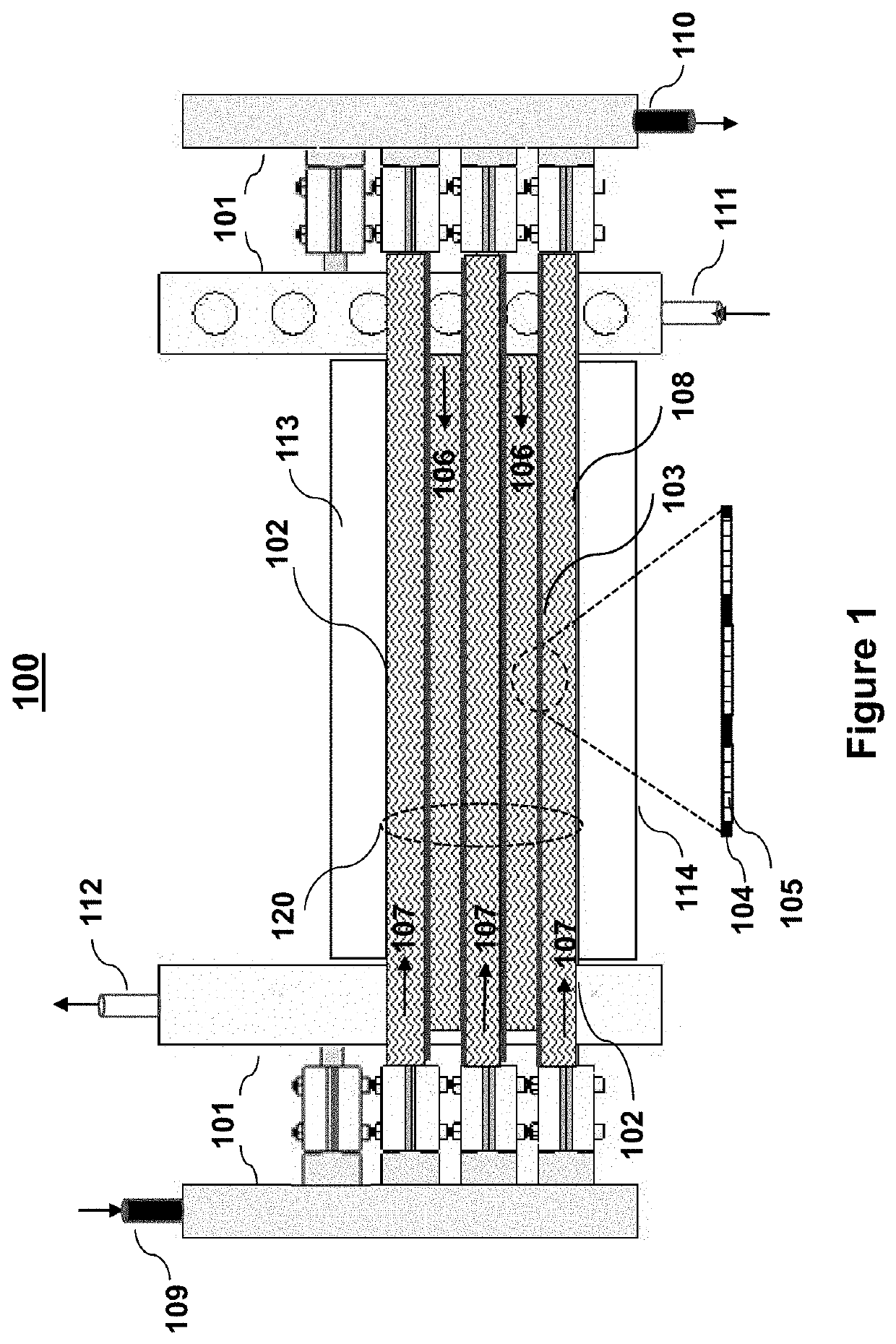
[0039]By way of example and not as a limitation, the basic concepts of the invention are illustrated using a most common Proton Exchange Membrane (PEM) fuel cell. In one embodiment of the invention shown in FIG. 1, a schematic cross-sectional view 100 of the f...


PUM

PropertyMeasurementUnit
polarityaaaaaaaaaa
electrical polarityaaaaaaaaaa
semi-permeableaaaaaaaaaa

Abstract

A lightweight electrochemical fuel cell suitable for modular stacking to achieve high output power is described. The electrochemical fuel cell is constructed of a stack of flexible polymer layers sealed at the periphery to create fuel and reactant channels. To scale up the output power, the electrochemical fuel cell is stacked on an external mechanical frame, wrapped-over on to itself in a self-supported 3-dimensional form, or wrapped over around a central mandrel to increase the active area of the fuel cell The electrochemical fuel cell has built in current collecting means and sealed electrodes to eliminate the need for bipolar plates, thereby enabling applications requiring high output power while maintaining a low weight. The thermal management is external to the fuel cell core structure to facilitate modular expansion of the stack to achieve high output power.

Description

CROSS-REFERENCE TO RELATED APPLICATIONS[0001]This application is related to the U.S. Provisional Patent Application No. 63 / 073,286 filed on Sep. 1, 2020, which is being incorporated by reference herein in its entirety.STATEMENT REGARDING FEDERALLY SPONSORED RESEARCH OR DEVELOPMENT[0002]Not Applicable.BACKGROUND OF THE INVENTIONField of the Invention[0003]This invention is related to the field of energy generation, and in particular to energy generation in a fuel cell by way of an electrochemical reaction with zero carbon emission. This invention is directed to a fuel cell design and an architecture suitable for construction of compact stackable fuel cells. The fuel cells described in this invention are flexible and modularly stackable without the bipolar plates that are typically used for current collection and mechanical support in prior art constructions.Related Background Art[0004]An electrochemical reaction in a fuel cell generates a potential difference between an anode and a c...

Claims


Application Information

Patent Timeline
Patent Type & Authority Applications(United States)
IPC IPC(8): H01M8/2484H01M8/0267H01M8/0258H01M8/242H01M8/0271H01M8/0236H01M8/0245
CPCH01M8/2484H01M8/0267H01M8/0258H01M8/0245H01M8/0271H01M8/0236H01M8/242H01M8/04007H01M8/023H01M8/0273Y02E60/50
Inventor GHOSH, CHUNI LAL
Owner GHOSH CHUNI LAL
Why Eureka
Try Eureka