Aerodynamic arm for an aircraft turbine engine casing

Pending Publication Date: 2022-02-24
SN DETUDE & DE CONSTR DE MOTEURS DAVIATION S N E C M A
View PDF4 Cites 0 Cited by
  • Summary
  • Abstract
  • Description
  • Claims
  • Application Information

AI Technical Summary

Benefits of technology

The invention is about a new design for an aerodynamic arm that can safely and efficiently pass high amounts of electrical power through a turbine engine. The arm is simple and doesn't increase the mass of the engine. It also includes an insulator to prevent electrical contact between the conductive core and the outer shell, ensuring the integrity of the electrical connections. The turbine engine can now pass more electrical energy through multiple, thin arms without adding extra weight or space.

Problems solved by technology

Thus, contrary to the solutions of the prior art, the overall volume available inside the arm can be used to pass a large quantity of electrical energy required for the operation of the hybrid turbine engines.

Method used


Image

  • Aerodynamic arm for an aircraft turbine engine casing
  • Aerodynamic arm for an aircraft turbine engine casing
  • Aerodynamic arm for an aircraft turbine engine casing

Examples


Embodiment Construction

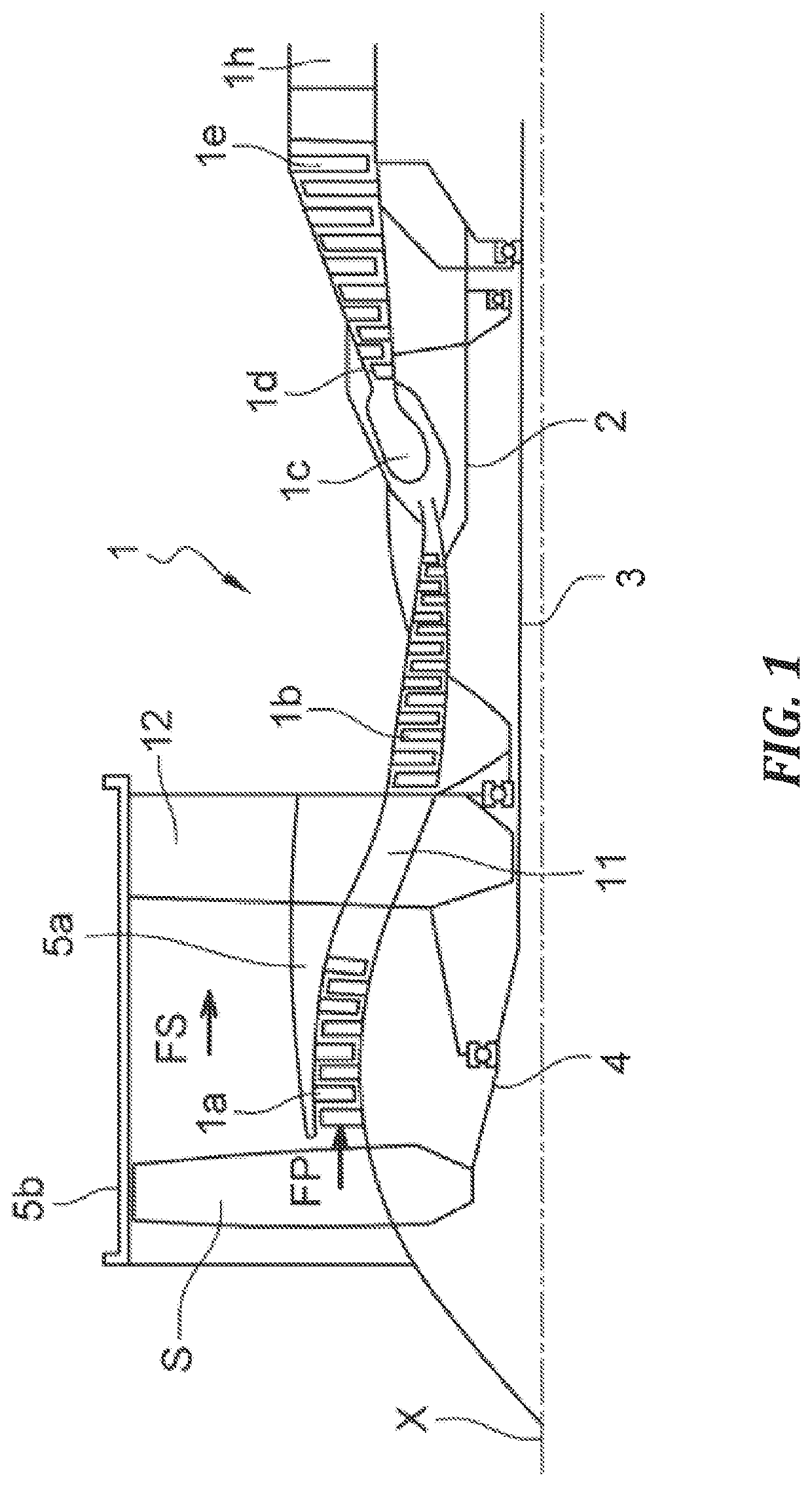
[0046]In this disclosure, the terms “upstream”, “downstream” are used in reference to the flow direction of the gas in an aircraft turbine engine. The terms “inner” and “outer” are defined with respect to a longitudinal axis of the turbine engine. The terms “axial”, “inside” and “outside” are defined with reference to the positioning of the components constituting the aerodynamic arm according to the invention.

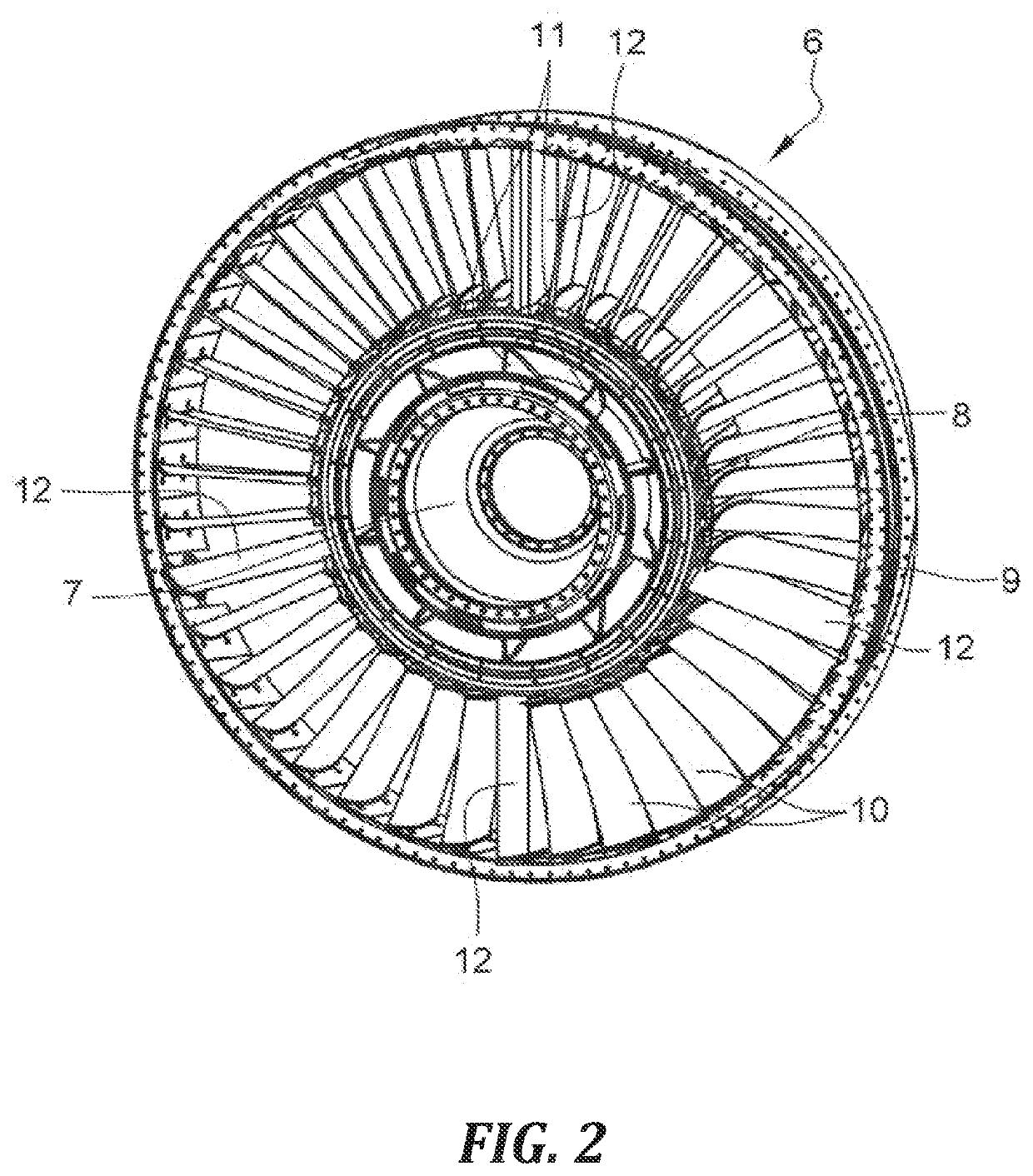
[0047]With reference to FIG. 2, a structural element of the turbine engine 1 designated intermediate casing 6 comprising two coaxial annular rows of blading constituting an inner blading located in the primary flow FP and an outer blading located in the secondary flow FS. More precisely, the intermediate casing 6 comprises a hub 7 intended to be traversed by the LP shaft 3, an inner ring gear 8 for separating the primary FP and secondary FS flows, an outer annular shroud 9 located at the level of a nacelle of the turbine engine, radial aerodynamic arms 10 in the form of fins e...


PUM


Abstract

An aerodynamic arm for an aircraft turbine engine casing includes a tubular outer shell having a generally elongate shape extending substantially along an axis. The shell has axial ends configured to be connected to a turbine engine casing. An electrically conductive core extends inside the shell and has ends configured to electrically connect to the ends of the shell. An insulating material occupies a space between the core and the shell.

Description

TECHNICAL FIELD OF THE INVENTION[0001]The present invention relates to the field of turbine engines. It relates to a casing aerodynamic arm for an aircraft turbine engine.BACKGROUND[0002]The prior art comprises in particular the documents US-A1-2014 / 193249 and US-A1-2012 / 266439.[0003]FIG. 1 shows a double flow turbine engine 1 which comprises, conventionally centred on a longitudinal axis X, a fan S, a low-pressure compressor 1a, a high-pressure compressor 1b, an annular combustion chamber 1c, a high-pressure turbine 1d, a low-pressure turbine 1e and an exhaust nozzle 1h. The high-pressure compressor 1b and the high-pressure turbine 1d are connected by a high-pressure shaft 2 and together form a high-pressure (HP) body. The low-pressure compressor 1a and the low-pressure turbine 1e are connected by a low-pressure shaft 3 and together form a low-pressure (LP) body. The fan S is driven by a fan shaft 4.[0004]The fan S delivers an annular airflow with a central annular part, called pri...

Claims


Application Information

Patent Timeline
IPC IPC(8): F01D5/14F04D29/54F04D29/02F01D5/28F01D9/04F02C7/20F02K3/06B33Y80/00
CPCF01D5/147F04D29/542F04D29/023F01D5/28F01D9/041B33Y10/00F02K3/06B33Y80/00F05D2220/323F05D2230/31F05D2240/12F02C7/20F01D9/04F05D2300/50F01D9/065F01D25/162Y02T50/60
Inventor MISSOUT, MARC
Owner SN DETUDE & DE CONSTR DE MOTEURS DAVIATION S N E C M A
Why Eureka
Try Eureka