Eureka AIR delivers breakthrough ideas for toughest innovation challenges, trusted by R&D personnel around the world.

Arrangement having store for electrical energy and regenerative energy generator, in particular a wind power plant, and method for operating same

a technology of electrical energy and regenerative energy generators, which is applied in the direction of greenhouse gas reduction, transportation and packaging, and load balancing of ac networks, etc., can solve the problems of reducing generation, oversupply, or shortage, and plants for regenerative energy generation can only provide balancing power, so as to achieve efficient and economical effects

Pending Publication Date: 2022-02-17
SIEMENS GAMESA RENEWABLE ENERGY SERVICE GMBH
View PDF0 Cites 0 Cited by
  • Summary
  • Abstract
  • Description
  • Claims
  • Application Information

AI Technical Summary

Benefits of technology

This patent is about a system for improving the operation of a power grid by using energy storage to shift power production to meet demand peaks. The system uses a correction unit that predicts the available power and makes adjustments to the regenerative energy generator to ensure the desired power is always available. The correction unit can take into account various input parameters, such as wind strength, sunshine intensity, demand, and the state of charge of the energy storage. By providing a reference signal for the setpoint power output, the system can achieve self-regulation and improve the overall stability of the grid.

Problems solved by technology

In the case of a negative operating reserve, the opposite is true: there is then too much power generation relative to power consumption, such that generation must be reduced.
An oversupply, or a shortage, of electrical power (active power) becomes noticeable through a change in grid frequency.
Such changes in grid frequency result from the fact that if there is a lack of active power in the grid (generation is too low), the synchronous generators slow down due to their design, or if there is too much active power (generation is too high for consumption), the synchronous generators are relieved and thus accelerate.
However, in electricity grids, conventional power plants with their large synchronous generators are increasingly being replaced by smaller decentralized power plants whose feed-in power depends on the primary energy supply (e.g. the wind speed).
Power plants for regenerative energy generation can only provide balancing power in dependence on the primary energy supply, and must be operated below the possible output (limited) if positive operating reserve is to be provided.
While conventional power plants are by their nature usually able to meet this requirement of guaranteed availability, this is usually not the case for regenerative energy generation plants.
In particular, regenerative energy generation plants lack a sufficiently reliable forecast for the required time period (the time period over which the availability of the operating reserve is guaranteed) and, moreover, these plants often cannot provide (or can provide only to a very limited extent) positive operating reserve (if the wind does not blow sufficiently, no additional power can be fed in).
However, the provision of the storage means is expensive and their utilization is sometimes not optimal.
This advantage is offset by the disadvantage that an additional element is required to dissipate excess energy; moreover, this dissipation of electrical energy due to the lack of possible storage means is a waste of energy, which is to be avoided.

Method used


Image

  • Arrangement having store for electrical energy and regenerative energy generator, in particular a wind power plant, and method for operating same
  • Arrangement having store for electrical energy and regenerative energy generator, in particular a wind power plant, and method for operating same
  • Arrangement having store for electrical energy and regenerative energy generator, in particular a wind power plant, and method for operating same

Examples


Embodiment Construction

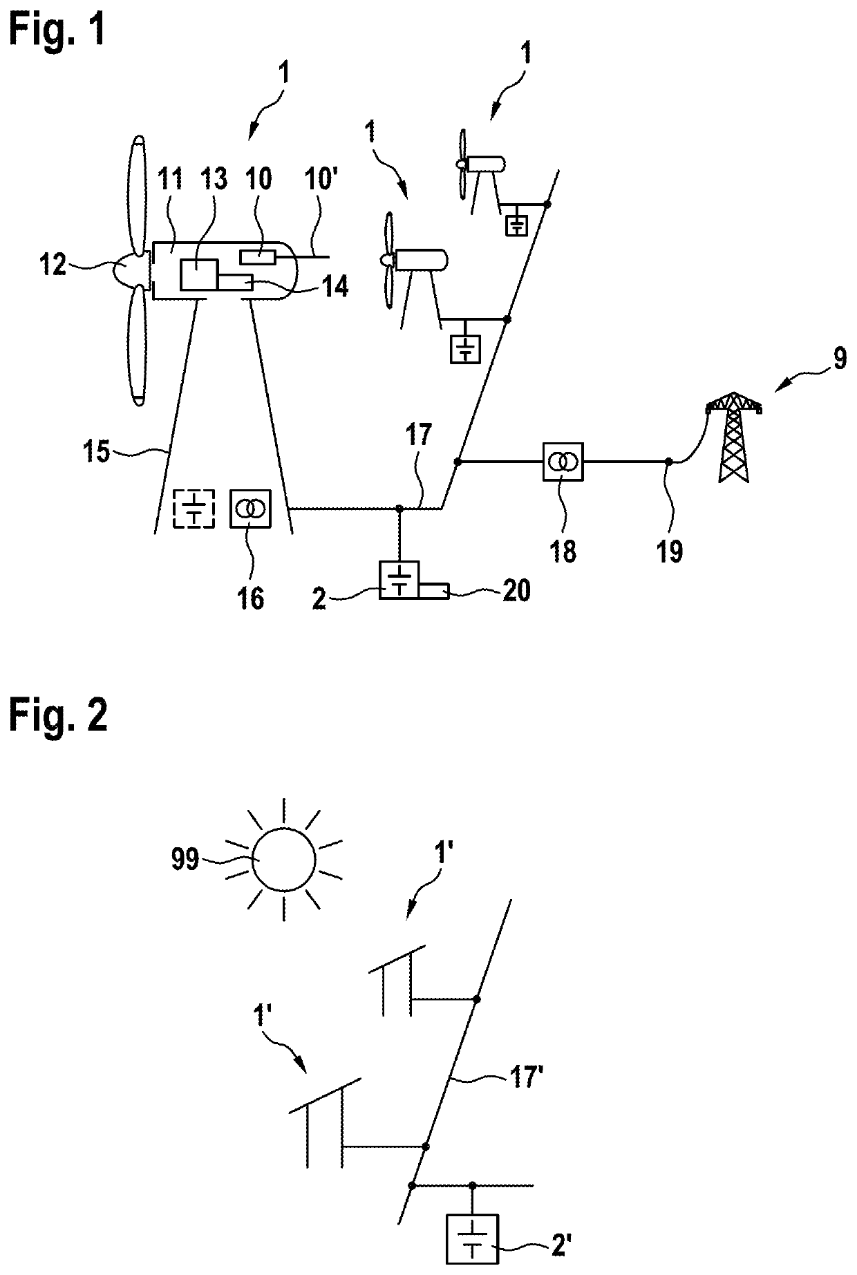
[0033]A wind power plant denoted in its entirety by the reference 1, together with a storage means 2, forms an arrangement according to an exemplary embodiment of the invention.

[0034]The wind power plant 1 is of a conventional design. It has a tower 15, at the upper end of which a nacelle 11 is arranged so that it can swivel in the azimuth direction. Rotatably arranged on one end of the nacelle is a wind rotor 12, which via a rotor shaft (not represented) drives a generator 13, which acts in combination with a converter 14 to generate electrical power. The thus generated electrical power is led via an internal line (not represented) to a system transformer 16 and, via a connection line 17, to a mostly park-internal central grid. The storage means 2 is also connected to the connection line 17. Further wind power plants 1 of the wind farm may also be connected, which are substantially of the same design and are expediently connected to a common storage means of the wind farm; however,...


PUM


Abstract

An arrangement comprising a regenerative energy generator and a store for electrical energy to be output to a grid, the regenerative energy generator including an energy converter for converting renewable energy sources into electrical energy and a power control unit which has an input for a target power output and controls the power generation by the regenerative energy converter, with a charge controller for the store also being provided, which sets a minimum operating reserve and outputs a signal for a target state of charge (SoC) of the store. In order to achieve improved utilization of the store, a correction unit is connected to the charge controller and continuously modifies the signal for the target state of charge (SoC). A sequence control unit is actuated by the correction unit and influences the power control unit of the regenerative energy generator according to an output value of the correction unit.

Description

CROSS-REFERENCE TO RELATED APPLICATIONS[0001]This application is a U.S. national stage application under 35 USC 371 of International Patent Application No. PCT / EP2019 / 082580, filed Nov. 26, 2019, which claims the priority of DE Application No. 10 2018 009 341.8, filed Nov. 28, 2018, the entire contents of each are incorporated herein by reference.FIELD OF THE DISCLOSURE[0002]The invention relates to an arrangement for energy generation and storage. It comprises a regenerative energy generator, in particular a wind power plant and / or a photovoltaic system, and a storage means for electrical energy.BACKGROUND OF THE DISCLOSURE[0003]To ensure a high level of supply security, electrical grids must be able to rapidly compensate for differences between, on the one hand, power generation and, on the other, power consumption. The electrical power required for this is called operating reserve. Positive operating reserve is needed to compensate for a usually sudden deficit in power generation...

Claims


Application Information

Patent Timeline
IPC IPC(8): H02J3/38H02J7/00H02J3/46
CPCH02J3/381H02J3/004H02J3/46H02J7/0048H02J3/32H02J2300/20H02J2300/28H02J7/00712Y02E70/30Y02E10/76Y04S10/50H02J7/34F03D9/11Y02E10/56H02J2203/10
Inventor SEIDEL, MATTHIASDIMOV, ATANAS
Owner SIEMENS GAMESA RENEWABLE ENERGY SERVICE GMBH
Why Eureka
Eureka Blog
Learn More