
Non-Loosening Bolt

a bolt and non-loosening technology, applied in the direction of fastening means, screws, threaded fasteners, etc., can solve the problems of momentari gap between the bolt, occurrence of loosening, poor ease of operation, etc., to achieve robust and reliable anti-loosening effect, easy and rapid operation, and the effect of comparatively easy and rapid bolt tightening

Pending Publication Date: 2022-02-17
TOKUMOTO TOSHIMITU
View PDF0 Cites 1 Cited by
  • Summary
  • Abstract
  • Description
  • Claims
  • Application Information

AI Technical Summary

Benefits of technology

The present invention provides a locking bolt that can be easily and rapidly tightened, and has a robust and reliable antiloosening effect when used as a nonloosening tap bolt. This is achieved by combining two bolt parts in a way that ensures they align with each other and act in the same direction when rotated. The misalignment in the radial direction provides the locking effect.

Problems solved by technology

When a tap bolt is subjected to vibration or impact, it is known that a gap can form momentarily between the bolt and the surface against which it is tightened, such that a load no longer acts on the bolt, in accompaniment to which rotation of the bolt may occur and there may be occurrence of loosening.
However, with the foregoing conventional locking-wire technique, not only are two bolts and two bolt holes required, but there has also been the problem that it is poor in terms of ease of operations, since it requires that an operation be carried out in which a wire is installed at the heads of the two bolts.

Method used


Image

  • Non-Loosening Bolt
  • Non-Loosening Bolt
  • Non-Loosening Bolt

Examples


working example 1

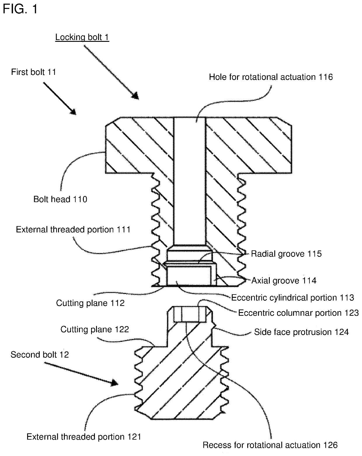
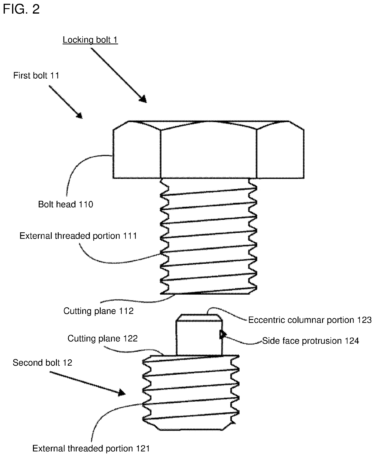
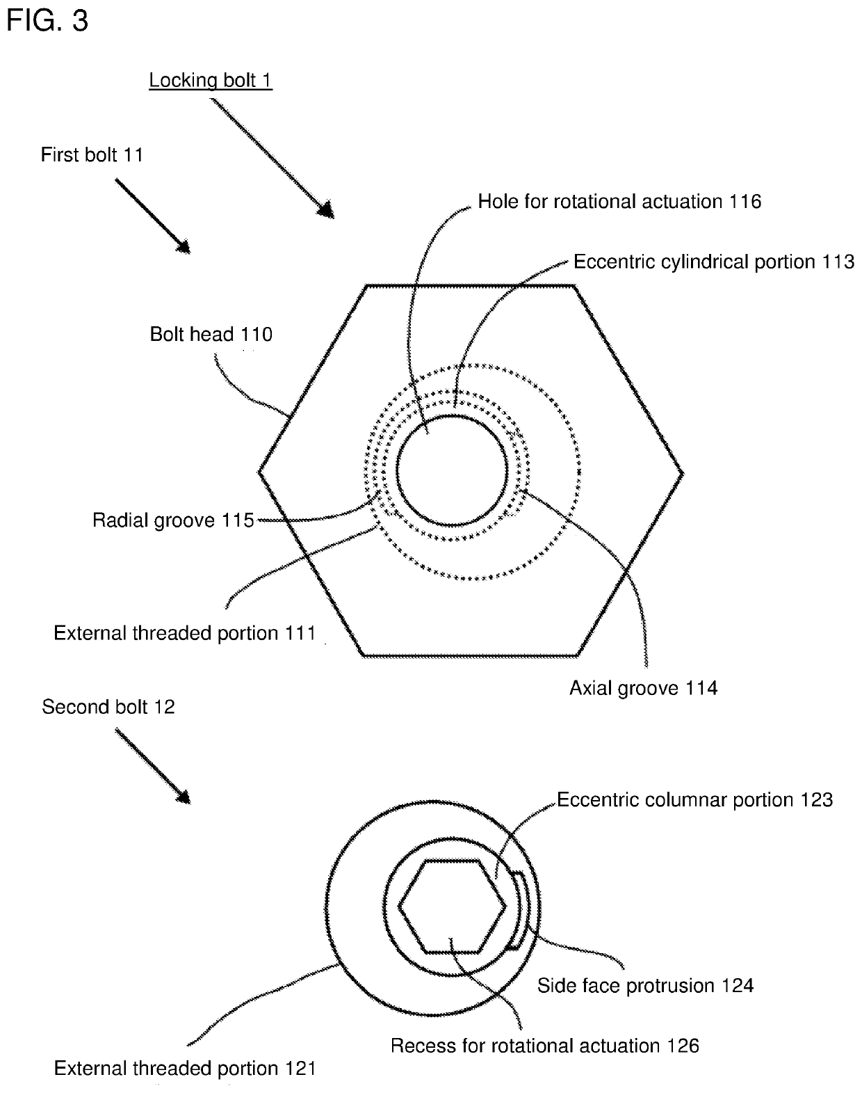
[0051]As shown by way of example in FIG. 1, locking bolt 1 comprises first bolt 11 and second bolt 12.

1. First Bolt 11

[0052]First bolt 11 has an external threaded portion 111 which is threaded for threaded engagement with bolt hole 13 at the outside circumference thereof. In accordance with the present embodiment, as viewed from the side, first bolt 11 is a bolt which is equipped with a bolt head 110 and which is equipped with a male-threaded external threaded portion 111 at the outside circumference thereof.

[0053]In addition, at first bolt 11, eccentric cylindrical portion 113 is formed at cutting plane 112 between it and second bolt 12.

[0054]Eccentric cylindrical portion 113 is smaller than the diameter of first bolt 11. Furthermore, eccentric cylindrical portion 113 is formed so as to be eccentric in a direction perpendicular to the central axis of first bolt 11, axial groove 114 which is parallel to the axial direction of first bolt 11 and radial groove 115 which is parallel to ...

working example 2

[0070]When as shown in FIG. 9 bolt hole 23 extends through member 24, permitting rotational actuation tool 25 to be used from a location below bolt hole 23, recess 225 for rotational actuation such as will permit rotational actuation from the exterior is provided at the threaded tip face on the side opposite cutting plane 122 at second bolt 22 as shown in FIG. 8.

[0071]As was the case at Working Example 1, after locking bolt 2 has been fastened within bolt hole 23, rotational actuation tool 25 is inserted by way of the hole made by the through-hole at the face on the side opposite the face against which locking bolt 2 is fastened within bolt hole 23 as shown in FIG. 9, and is captured by recess 225 for rotational actuation at second bolt 22, and only second bolt 22 is made to rotate relative to first bolt 21 by a prescribed angle in the same direction as the direction that would cause tightening of first bolt 21.

[0072]By so doing, the locking effect due to the misalignment in the rad...

working example 3

[0073]As shown in FIG. 10 and FIG. 11, by providing eccentric columnar portion 326 for rotational actuation which is a rod that is integral to the recess permitting rotational actuation at eccentric columnar portion 123 provided at cutting plane 122 of second bolt 32, eccentric columnar portion 326 for rotational actuation is such that when eccentric columnar portion 123 is captured by eccentric cylindrical portion 113 until a state is reached in which cutting plane 112 and cutting plane 122 come in contact, this will make it possible to carry out rotational actuation of second bolt 32 from the exterior inasmuch as it can be made to emerge to the exterior of first bolt 11 as a result of being made to pass through hole 116 for rotational actuation which extends all the way through first bolt 11, making it possible for the tightening procedure and locking procedure to be carried out with respect to locking bolt 3 using only two sizes of spanner / wrench, as a result of which it will be ...


PUM


Abstract

Provided in the context of a bolt is a method for achieving antiloosening capability such as will make it possible for tightening operations to be carried out easily and rapidly, and such as will make it possible to obtain antiloosening effect in robust and reliable fashion. Comprised, in such form as if a single bolt had been cut into two perpendicularly with respect to an axis thereof at a location midway along the axis thereof, of first bolt 11 having a bolt head and second bolt 12 having a threaded tip; second bolt 12 being such that an eccentric columnar portion 123 which is smaller in diameter than a diameter of the shaft of the second bolt 12 is provided at cutting plane 122 in such fashion as to protrude outward in an axial direction in eccentric fashion with respect to a direction perpendicular to a central axis, and such that side face protrusion 124 is formed at an outside circumferential side face of eccentric columnar portion 123; first bolt 11 being such that eccentric cylindrical portion 113 that mates with eccentric columnar portion 123 is formed at cutting plane 112 in eccentric fashion with respect to a direction perpendicular to a central axis, axial groove 114 being formed in a direction parallel to the central axis and radial groove 115 being formed in a radial direction at the interior thereof; the entirety constituting locking bolt 1.

Description

INCORPORATION BY REFERENCE[0001]This application is a continuation-in-part of and claims benefit under 35 USC 120 and 365(c) to copending International Application No. PCT / JP2020 / 016737, entitled “Non-Loosening Bolt”, filed 16 Apr. 2020; and further claims benefit of priority under 35 USC 119(a)-(d) to Japanese Patent Application No 2019-087074, entitled “Non-Loosening Bolt”, filed 30 Apr. 2019, the contents of both of which applications are incorporated herein in their entireties by reference.TECHNICAL FIELD[0002]The present invention relates to a nonloosening bolt. In particular, it relates to a bolt which has antiloosening capability and which may be used as a tap bolt.BACKGROUND ART[0003]When a tap bolt is subjected to vibration or impact, it is known that a gap can form momentarily between the bolt and the surface against which it is tightened, such that a load no longer acts on the bolt, in accompaniment to which rotation of the bolt may occur and there may be occurrence of lo...

Claims


Application Information

Patent Timeline
Patent Type & Authority Applications(United States)
IPC IPC(8): F16B39/34F16B39/282F16B35/00
CPCF16B39/34F16B35/00F16B39/282F16B39/02
Inventor TOKUMOTO, TOSHIMITU
Owner TOKUMOTO TOSHIMITU
Learn More