
Cylindric drum with sanding elements

a technology of sanding elements and cylindrical drums, applied in the direction of brushes, gear teeth, applications, etc., can solve the problems of cumbersome and time-consuming, and achieve the effect of convenient and rapid operation

Inactive Publication Date: 2005-07-07
JESPERSEN POUL ERIK
View PDF12 Cites 1 Cited by
  • Summary
  • Abstract
  • Description
  • Claims
  • Application Information

AI Technical Summary

Benefits of technology

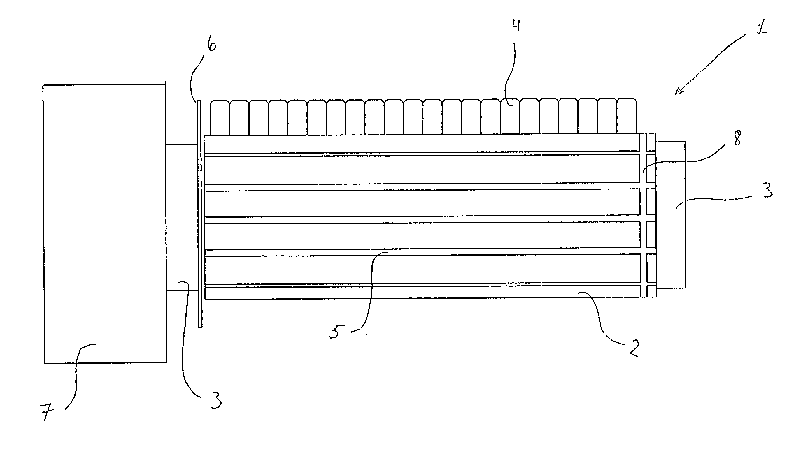
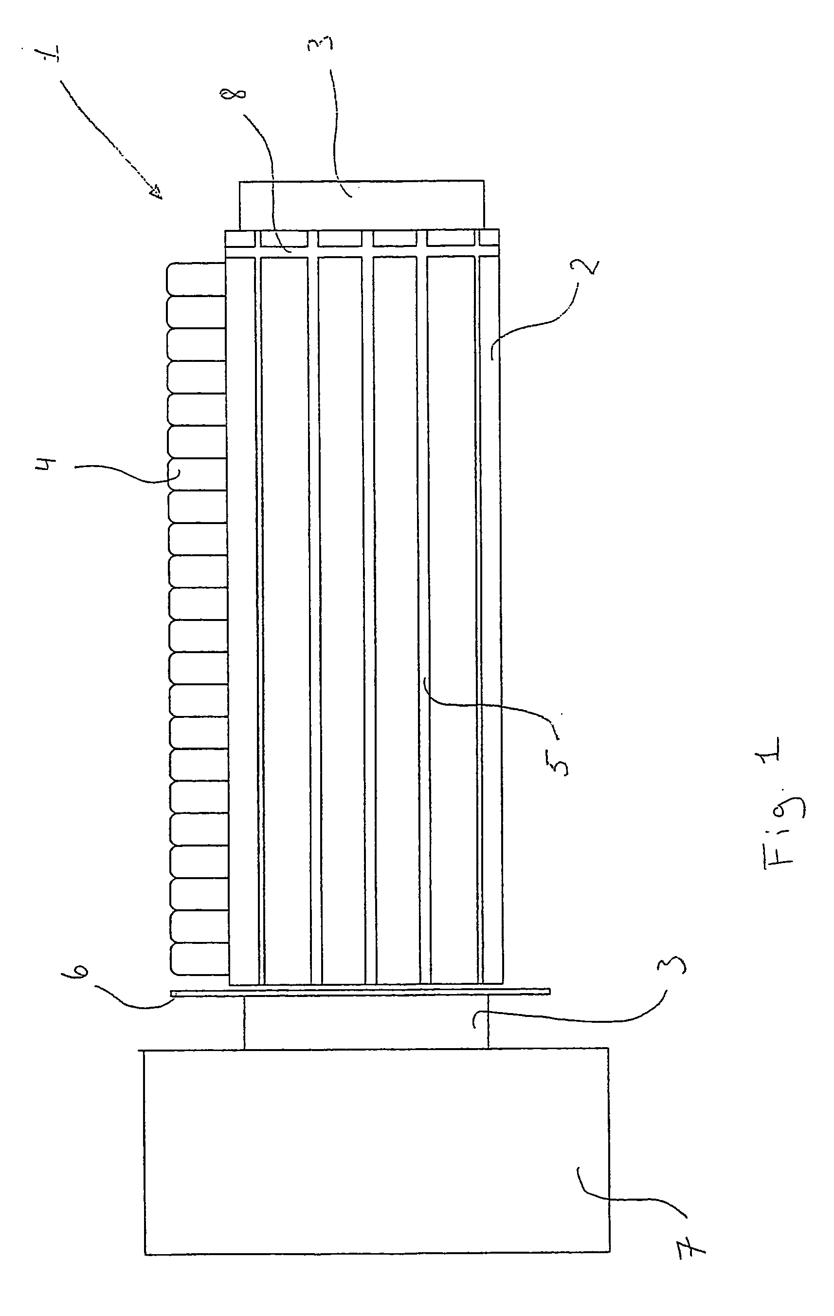
[0005] It is therefore the purpose of the invention to provide a cylindric drum that enables secure retention of the longitudinally displacing sanding elements during use of the sanding / polishing tool and which by replacement of the sanding elements is easily and rapidly operated.
[0019] Alternatively, in an embodiment there may be used a strap which is placed and clamped in the annular groove. In order to replace the longitudinally displacing sanding elements, the strap may typically be broken. This provides that the strap is to be produced inexpensively and not be complicated This strap may e.g. be a clamp, a rubber band, a cord, and / or a strip.
[0021] This embodiment of the cylindric drum will be applied when using sanding / polishing tools employing cylindric drums with large diameter and / or have significant length. Instead of making the cylindric drum with a groove, it will be easy to use an elastic means which by means of an axial contraction, elasticity and friction will retain the moulds of the sanding elements in the undercut grooves in the cylindric drum.

Problems solved by technology

However, this has the drawback that in order to replace the sanding elements in the cylindric drum, the arrangement with the releasable plate has to be taken apart, which may be cumbersome and time-consuming.

Method used


Image

  • Cylindric drum with sanding elements
  • Cylindric drum with sanding elements
  • Cylindric drum with sanding elements

Examples


Embodiment Construction

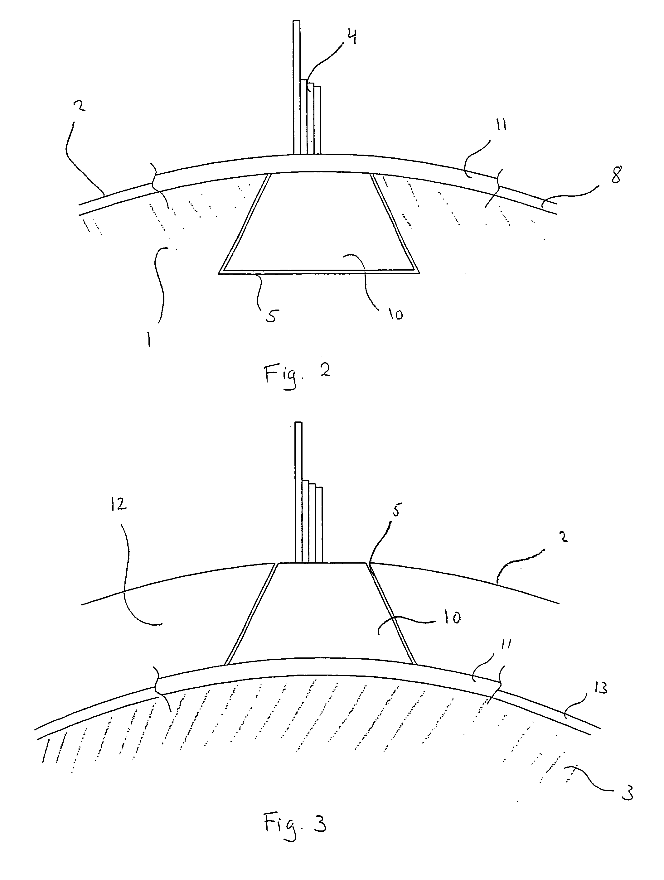
[0007] Alternatively, this may be achieved with one cylindric drum being characterised in that there is provided an elastic means with bearing against the drum surface or the shaft surface and preferably perpendicularly to the rotational axis of the cylindric drum and along the periphery of either the drum surface or the surface of the shaft, where at least a part of the elastic means abuts on a part of the mouldings of the sanding elements that are mounted in the axial, undercut grooves.

[0008] In order to achieve securing of longitudinally displacing mouldings in the undercut axial grooves in the cylindric drum, the drum is designed with an annular groove perpendicularly to the rotational axis of the cylindric drum and along the periphery of either the drum surface or the shaft surface in which it is possible to provide a stop means arranged to be accommodated in the annular groove in an axially fixed position. As at least a part of the stop means is in contact with end faces of t...


PUM


Abstract

The invention concerns a cylindric drum for a sanding / polishing tool which in its drum surface is provided with a number of undercut axial grooves for mounting one or more axially displaceable sanding elements, where an annular groove has been provided either in the drum surface or a shaft perpendicularly to the rotational axis of the cylindric drum and along the periphery of either the surface of the drum or the surface of the shaft, that a stop means has been arranged for accommodation in the annular groove in an axially fixed position, where at least a part of the stop means abuts on end faces of the moldings of the sanding elements mounted in the axial undercut grooves.

Description

FIELD OF THE INVENTION [0001] The present invention concerns a cylindric drum for a sanding / polishing tool which in its drum surface is provided with a number of undercut axial grooves for mounting one or more axially displacing sanding elements. BACKGROUND OF THE INVENTION [0002] By using cylindric drums for sanding / polishing tools having undercut and through-going grooves in the surface of the cylindric drum, thus enabling fitting and replacing sanding elements sliding longitudinally, it is necessary that the longitudinally displacing sanding elements are held in place during use of the sanding / polishing tool. [0003] Normally, at one end of the cylindric drum there will be an arrangement with a plate and a means for fastening the cylindric drum to a drive unit, e.g. a gearbox and / or a motor. At the other end of the cylindric drum there will be a second arrangement with a releasable plate and possibly a means for fastening the cylindric drum to a support unit. [0004] However, this ...

Claims


Application Information

Patent Timeline
Patent Type & Authority Applications(United States)
IPC IPC(8): A46B7/04A46B13/00B24D9/04B24D13/06
CPCA46B7/04A46B13/001B24D13/06B24D9/04A46B2200/3093
Inventor JESPERSEN, POUL ERIK
Owner JESPERSEN POUL ERIK
Learn More