
Dry well temperature calibrators, cooling systems, and methods

a temperature calibrator and dry well technology, applied in the direction of thermometer testing/calibration, instruments, heat measurement, etc., can solve the problems of multiple problems and drawbacks of known temperature calibrators and wells, safety hazards for operators, and inadvertent cooling of wells

Pending Publication Date: 2022-02-10
KING NUTRONICS LLC (A DELAWARE LLC)
View PDF0 Cites 2 Cited by
  • Summary
  • Abstract
  • Description
  • Claims
  • Application Information

AI Technical Summary

Benefits of technology

The present patent is about an improved dry well temperature calibrator system that solves various problems and drawbacks associated with existing temperature calibrators and wells. The system is designed to require less energy to operate, and can quickly cool down the well to a safe temperature. It also reduces the risk of injury to operators, prevents damage to the surrounding environment, and ensures accurate temperature readings. The technical effects of the patent include improved safety, efficiency, and accuracy of temperature calibration.

Problems solved by technology

However, the flow inadvertently also cools down the well.
However, the hot air still flows upward during most of the calibration cycle.
Known temperature calibrators and wells suffer from multiple problems and drawbacks.
The hot air flowing upward from the top of the well creates a safety hazard to operators.
Given the high temperature of discharged air, and the fact that the system's display may be located near the well opening, even an insignificant draft of hot discharged air can cause burns or discomfort to the operator and other persons, and / or damage to the surrounding environment.
This can have a significant negative effect on the energy efficiency of the system and / or can require increased operational power requirements.
This can be a significant concern, such as when the system is being used in windy condition (e.g., marine applications) since the sudden change of temperature might affect the UUT reading accuracy.
The hot air may heat up the circuits thus affecting the reading, or cause other problems.
Transitioning the shutter door between open and closed positions can result in a change (e.g., reversal) of the direction of the airflow passing through the heat chamber.

Method used


Image

  • Dry well temperature calibrators, cooling systems, and methods
  • Dry well temperature calibrators, cooling systems, and methods
  • Dry well temperature calibrators, cooling systems, and methods

Examples


Embodiment Construction

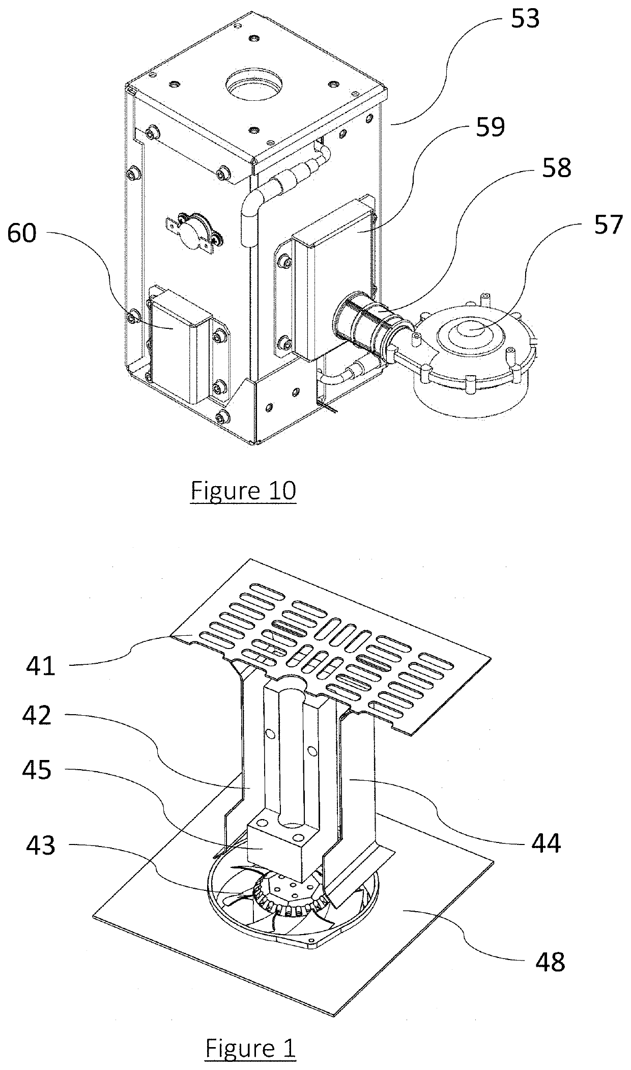
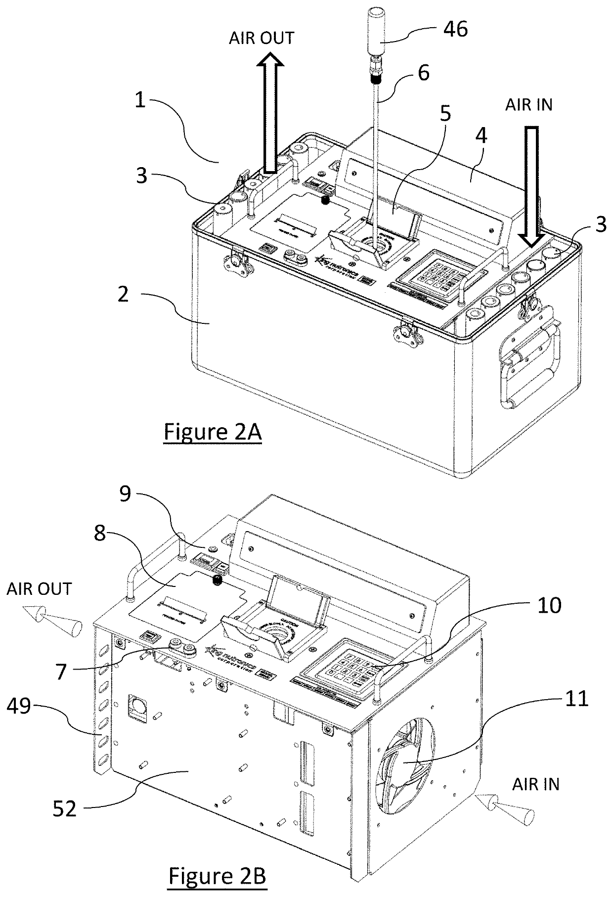
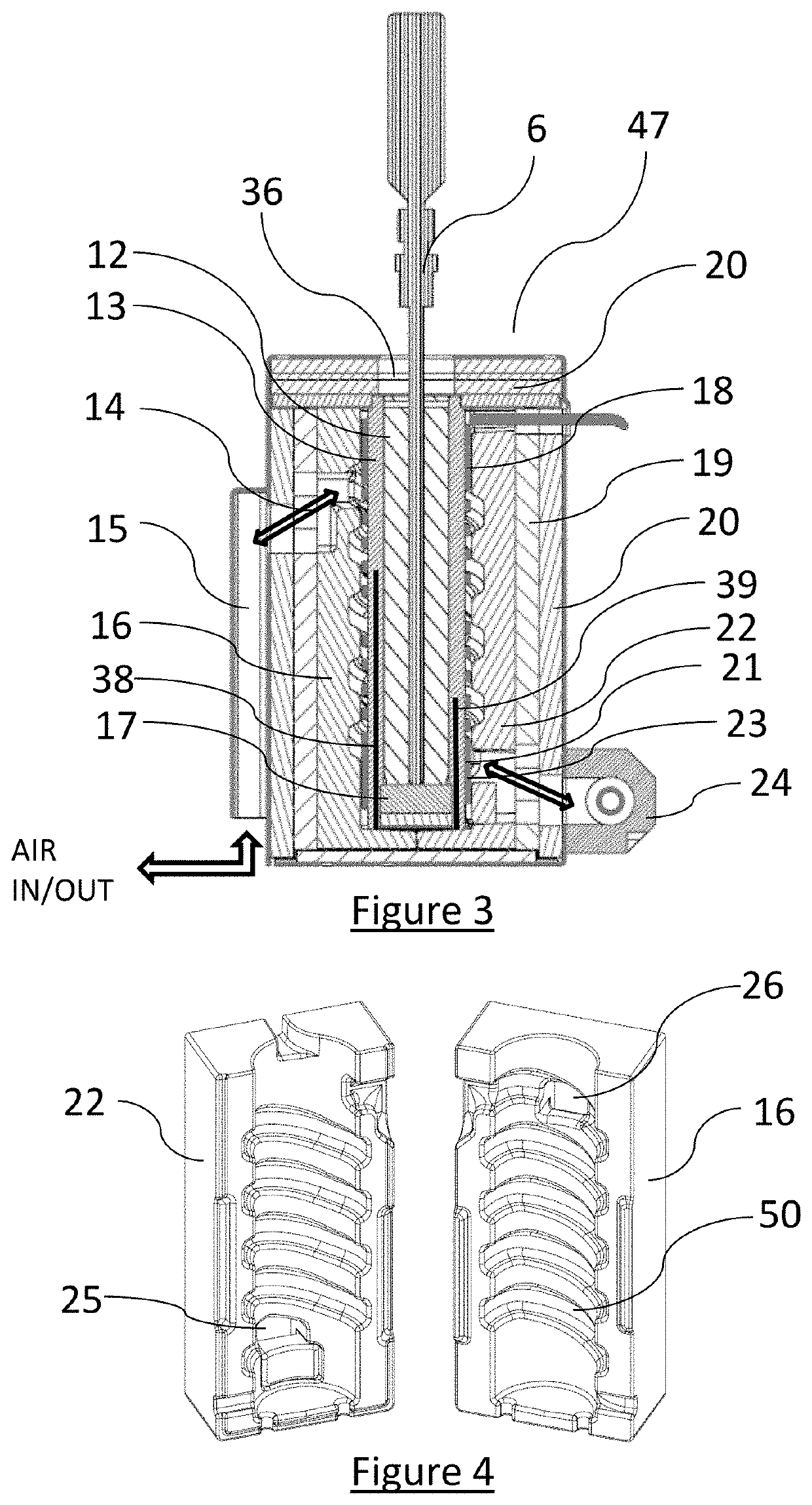
[0045]Various dry well temperature calibration systems are described. The dry well temperature calibration system can include an innovative dry well that is capable of rapidly heating and / or cooling, and / or of maintaining a stable and accurate temperature while soaking at the designated set point in lab and field applications. Several embodiments of the system enhance safety, such as by not discharging dangerously hot air. Some embodiments have a negligible impact on the temperature of the surrounding environment. The system can be adapted to enable energy efficient operation, such as at least partly due to hybrid power (AC / DC) control and / or a sealed well. In some embodiments, a small portable battery, such as a 1000 Wh, 270,000 mAh lithium-ion battery pack, can power the system for several hours (e.g., such as at least about 8 hours) of continuous operation of typical operational cycles. Certain implementations of the system have other benefits, such as increased convenience, accu...


PUM

PropertyMeasurementUnit
threshold temperatureaaaaaaaaaa
temperatureaaaaaaaaaa

Abstract

Various dry well temperature calibration systems, as well as other temperature control systems, are disclosed. The system can include a well configured to receive a unit under test, a heater configured to heat the well, and a temperature sensor configured to detect a temperature of the well. The system can include a helical airflow groove around the well. A venturi pump unit can be in fluid communication with the airflow groove. The venturi pump unit can be configured to draw a flow of air through the airflow groove, thereby cooling the well.

Description

CROSS REFERENCE[0001]This application claims the priority benefit of U.S. Provisional Patent Application No. 63 / 061,649, filed Aug. 5, 2020, the entirety of which is incorporated by reference herein.BACKGROUNDField[0002]The present disclosure relates to improved dry well temperature calibrators, as well as other temperature control systems, such as systems for controlling and / or cooling kilns, ovens, etc.Certain Related Art[0003]Dry well temperature calibrators are used for calibrating temperature indicating or responsive devices like thermometers, sensors, switches, and other instruments. The temperature calibrator is comprised of a metallic mass with a cavity and an opening that enables insertion of a unit under test (UUT), such as a thermometer or temperature switch. The well has one or more heating elements and at least one internal temperature sensor that can precisely measure the well temperature. An electrical control system reads the temperature sensor output and controls th...

Claims


Application Information

Patent Timeline
Patent Type & Authority Applications(United States)
IPC IPC(8): G01K15/00
CPCG01K15/002G01K15/005
Inventor GNESSIN, AMIRLEW, TERRY C.RANSOM, NATHAN J.SOFFER, GUY
Owner KING NUTRONICS LLC (A DELAWARE LLC)
Learn More