Syringe and gasket systems

Pending Publication Date: 2022-02-10
SI02 MEDICAL PRODS
View PDF0 Cites 0 Cited by
  • Summary
  • Abstract
  • Description
  • Claims
  • Application Information

AI Technical Summary

Benefits of technology

This patent discusses an improved process for making gaskets with channels on their surface for use in syringe systems. These gaskets have better prevention of leakage and can be used in plastic syringes, which have superior container closure integrity and minimize interaction with the product. The process uses laser cuts and ensures minimal particles and optimal compression of the syringe and gasket system for improved performance and protection of the enclosed product. Overall, this patent provides an improved solution for producing reliable and efficient syringes and gaskets for use in healthcare settings.

Problems solved by technology

The need for relatively elevated forces to advance the gasket and plunger in the syringe may increase the user's difficulty in administering the injection product from the syringe.
This is particularly problematic for auto injection systems where the syringe is placed into the auto injection device and the gasket is advanced by a fixed spring.
However, use of flowable lubricant between the gasket and the barrel is not desired.
One reason is that a flowable lubricant can mix and interact with the drug product in a syringe, potentially degrading the drug or otherwise affecting its efficacy and / or safety.
For example, silicone oil, when used as a lubricant, can cause droplets which could potentially result in aggregation of sensitive biopharmaceuticals or clouding of the solution (Bee J S et al.
Monoclonal antibodies, conjugate vaccines, and protein formulations are particularly vulnerable to silicone-induced protein aggregation and particle formation.
In addition, over time, silicone migration can impact consistency of delivery, as it may change break loose and glide force (BLGF) and injection time (Thornton J D et al., 2015.
Subvisible particles caused by the migration of silicone oil into the drug formulation can introduce several product quality concerns, such as exceedance of USP limits for particulates in parenteral containers, structural instabilities in proteins caused by adsorption, and / or immunogenic responses caused by injection of silicone oil induced protein aggregates or silicone oil / protein complexes, which can reduce drug efficacy and / or cause potentially dangerous reactions in the patient, making the product unfit for use (Thornton J D et al., 2015.
Thus, lubricants may be problematic if they are injected into the patient along with the drug product.
In addition, flowable lubricants, when used with prefilled syringes, may migrate away from the gasket over time, resulting in spots between the gasket and the interior surface of the container with little or no lubrication.
However, such gaskets have experienced failures in CCI due to film wrinkling, defects in the film and / or film delamination from the rubber gasket may also have inferior gas-barrier properties.
Accordingly, a conventional fluoropolymer film laminated gasket alone may not be a viable solution for a prefilled syringe that houses product which is sensitive to certain gases.
Moreover, such a syringe and gasket system has inferior CCI.
However, this method of securing the gasket during the laser process has several disadvantages because the walls of the gasket may deform or sag while the gasket is being rotated to create the laser-cut groove.
This results in a less consistent laser cut or groove on the gasket film.
A syringe system incorporating a gasket produced by the process of U.S. patent application Ser. No. 15 / 445,108 is also more prone to liquid or gas leakage and has an inferior CCI.

Method used


Image

  • Syringe and gasket systems
  • Syringe and gasket systems
  • Syringe and gasket systems

Examples


process embodiments

Laser Process Embodiments

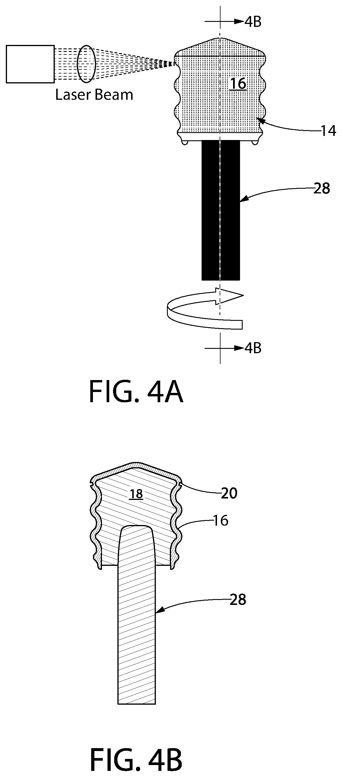
[0071]FIG. 4A, is a diagram of the laser processing process of one embodiment of the disclosure. Referring to FIG. 4A, a laser beam is applied at a desired angle to the circumferential surface portion of a gasket 14 which is secured on a mandrel 28. For the formation of channels in the circumferential surface portion of the gasket, a laser beam source is fixed with respect to the circumferential surface portion of the gasket 14 with a film 16 residing on the outer surface of the gasket, and the laser beam is applied to the circumferential surface portion while the gasket 14 secured to the mandrel 28 is rotated about the longitudinal axis thereof. Thus, the laser beam can be applied at the predetermined incident angle α to any angular position of the circumferential surface portion, whereby the channel is formed uniformly.

[0072]While the laser beam is applied obliquely to the circumferential surface portion, the gasket is rotated in a rotation direction such ...

example 1

I Test Method

[0089]Syringe and gasket systems of the disclosure are filled with water and the stoppers are vacuum loaded. The syringes are stored needle-end up at 4° C. Each syringe is removed at specific time-points (0 days, 1 day, 4 days, 7 days, 1 month, and 3 months), allowed to reach room temperature, and then visually inspected for signs of water that has entered the space between the ribs of the stopper. A text description of each failure is recorded and a photo is taken of each failure. The leakage properties of the syringes of the present disclosure are compared with the leakage properties of other syringes with gasket films (such as a laminated film). The syringes of the present disclosure have superior CCI over time compared to syringes that were not produced by the improved laser and inspection process of the disclosure.


PUM

PropertyMeasurementUnit
Lengthaaaaaaaaaa
Lengthaaaaaaaaaa
Lengthaaaaaaaaaa

Abstract

A process for producing gaskets with an improved channel for use in matched syringe and plunger systems, preferably prefilled plastic syringe systems. In particular, an improved process for making and inspecting continuous channels in a gasket film by laser treatment. The gaskets are useful in matched syringe and plunger systems with high and consistent container closure integrity (CCI), and consistent break loose and glide forces over time, and sealability.

Description

[0001]This application incorporates by reference in their entirety U.S. Provisional Application No. 62 / 776,958, filed Dec. 7, 2018; U.S. Provisional Application No. 62 / 788,168, filed Jan. 4, 2019; U.S. Provisional Application No. 62 / 789,366, filed Jan. 7, 2019; U.S. Provisional Application No. 62 / 825,166, filed Mar. 28, 2019; and U.S. Pat. No. 7,985,188 B2, issued Jul. 26, 2011. The application more particularly incorporates by reference U.S. Pat. No. 7,985,188 B2 for its disclosure of a syringe barrel or the like, lubricated by applying a PECVD coating of SiOxCy or SiOxCyHz, and for methods of making, testing and using such syringe barrels.FIELD[0002]The present disclosure relates to a matched syringe and plunger system, in particular a gasket to be used within the syringe, and an improved process of making and inspecting laser cuts in the gasket.BACKGROUND OF THE DISCLOSURE[0003]Prefilled parenteral containers, such as syringes or cartridges, and plunger systems have been develope...

Claims


Application Information

Patent Timeline
IPC IPC(8): A61M5/315B23K26/08B23K26/364B23K26/402
CPCA61M5/31513B23K26/0823A61M2005/3101B23K26/402A61M2207/00B23K26/364A61M2205/0222A61M2205/0238B23K2103/42
Inventor ABRAMS, ROBERT S.KELLY, KENNETH WADETAHA, AHMADHUNT, BENJAMINLILLY, BRIAN RUSSELLKIBELE, RALF
Owner SI02 MEDICAL PRODS
Why Eureka
Try Eureka