
Strip-form acoustic material having an integrated flange, and internal wall of an aircraft air intake made with this material

Pending Publication Date: 2022-02-03
AIRBUS OPERATIONS SAS
View PDF0 Cites 0 Cited by
  • Summary
  • Abstract
  • Description
  • Claims
  • Application Information

AI Technical Summary

Benefits of technology

The invention proposes a new acoustic material for making the internal wall of an air intake that is simple and low-cost to produce on an industrial scale. This material makes it possible to create an air intake with an increased acoustic treatment length, which results in improved performance. The invention also includes a new method for manufacturing the internal wall of an air intake that is simple and reduces mass and increases acoustic performance. Additionally, the invention includes strips of resistive skin with an integrated fastening flange that can be manufactured in significant quantities and at low cost. The presence of the integrated fastening flange allows for an increased acoustic treatment length and eliminates the need for shrouds at one end of the duct. The strip-form material has swage at its edges, making it easier to assemble two strips that follow one another in the air intake's orbital direction.

Problems solved by technology

This feature does not prevent the strips from being manufactured in kilometers at low cost.

Method used


Image

  • Strip-form acoustic material having an integrated flange, and internal wall of an aircraft air intake made with this material
  • Strip-form acoustic material having an integrated flange, and internal wall of an aircraft air intake made with this material
  • Strip-form acoustic material having an integrated flange, and internal wall of an aircraft air intake made with this material

Examples


first embodiment

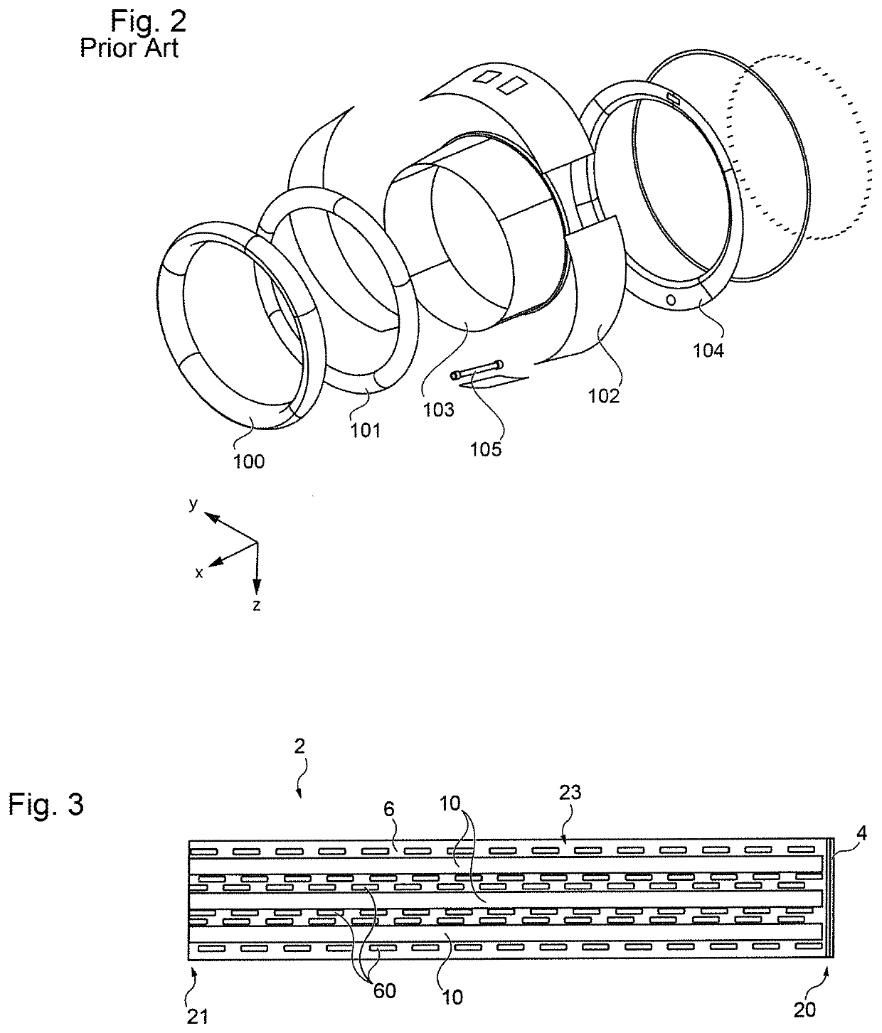
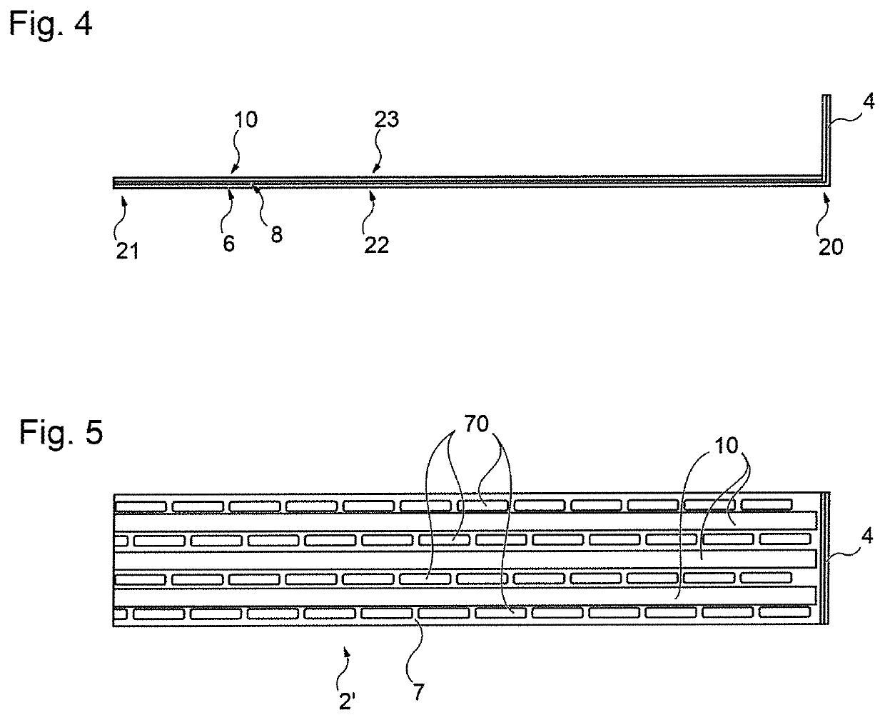
[0044]FIGS. 3 and 4 show a strip of material according to the invention. The material is in the form of a strip 2 which, in the example, is a multilayer strip, comprising a first layer 6 made of fiber-reinforced polymer, i.e., a layer of fibers embedded in a polymerized resin. The fibers may be chosen from carbon fibers, glass fibers, Kevlar fibers, etc., while the polymer may be chosen from thermoplastic resins such as the resins from the family of polyether ether ketones (PEEKs) and resins from the family of polyetherimides (PEIs).

[0045]This first layer 6 extends over the entire surface area of the strip of material; it determines the frontal dimensions (width and length) of the strip. The first layer 6 also forms a first frontal face 22 of the strip, which is intended to be the visible face of an aircraft air intake internal wall and to be in contact with an aerodynamic flow.

[0046]The first layer 6 has micro-perforations 60 that are elongate, rectangular in the example (in top vi...

second embodiment

[0055]FIG. 5 illustrates a strip of material according to the invention. This strip 2′ differs from the strip 2 only in that the first layer 7, which may be similar to the above-described first layer 6 in terms of material, is provided with perforations 70 that are elongate, for example rectangular or elliptical, instead of the micro-perforations 60. These elongate perforations advantageously have a width of between 1 mm and 3 mm, preferably between 1.5 mm and 2 mm, and a length of between 10 mm and 40 mm, preferably between 20 mm and 30 mm. Here too, no perforations are provided in the first layer 7 next to the tapes 10.

[0056]The profile view of this second embodiment is identical to that of the first embodiment and can therefore be seen in FIG. 4.

[0057]Such a strip-form material can easily be produced in kilometers.

[0058]To this end, for example:[0059]use is made of:

[0060]a first ribbon of fiber-reinforced polymer corresponding to the first layer, packaged as a first roll,

[0061]a ...


PUM

PropertyMeasurementUnit
Lengthaaaaaaaaaa
Thicknessaaaaaaaaaa
Widthaaaaaaaaaa

Abstract

A strip-form acoustic material, the strip having a length in a longitudinal direction, a width in a transverse direction, a thickness and axial ends. At least one of the axial ends of the strip, in an end portion of the length of the strip, the strip of material is folded in a substantially transverse plane.

Description

CROSS-REFERENCES TO RELATED APPLICATIONS[0001]This application claims the benefit of the French patent application No. 2008163 filed on Jul. 31, 2020, the entire disclosures of which are incorporated herein by way of reference.FIELD OF THE INVENTION[0002]The present application relates to a strip-form acoustic material and to a resistive skin manufactured from this material. The invention applies more particularly to the manufacture of the internal wall of the air intake of the aircraft nacelles.BACKGROUND OF THE INVENTION[0003]It will be recalled that an aircraft nacelle comprises, from the front to the rear, a first portion in the upstream direction of the aerodynamic flow, known as the air intake, a second portion that covers the casing of the engine fan, known as the fan cowl, and a third portion that generally has a thrust reversal zone which surrounds the engine turbine body in the downstream direction of the aerodynamic flow.[0004]An air intake, such as the one illustrated in...

Claims


Application Information

Patent Timeline
IPC IPC(8): F02C7/04B64D33/02B64D29/00B32B3/14B32B3/04B32B3/06B32B3/26B32B15/02B32B5/02B32B5/26B32B1/08G10K11/16
CPCF02C7/04B32B2597/00B64D29/00B32B3/14B32B3/04B32B3/06B32B3/266B32B15/02B32B5/02B32B5/26B32B1/08G10K11/16B64D2033/0206F05D2220/323B32B2307/102B32B2605/18B32B2260/021B32B2260/046B32B2262/103B64D33/02B64D29/06B32B27/285B32B27/281B32B27/12B32B15/18B32B15/08B32B27/08B32B3/26B32B33/00B32B2262/106B32B2262/101B32B2262/0269F02C7/045G10K11/168F02K1/827
Inventor PORTE, ALAINLALANE, JACQUES
Owner AIRBUS OPERATIONS SAS
Learn More