Tank used in engine cooling system, engine cooling system, and work machine

a technology for engine cooling and work machines, which is applied in the direction of engine cooling apparatus, machines/engines, cylinders, etc., can solve the problems of engine overheating, engine heat generated during operation cannot be fully taken away, and the heat exchange performance of the engine is reduced, so as to reduce the impact of the heat exchanger, avoid affecting the heat dissipation, and facilitate installation, transportation and storag

Active Publication Date: 2022-01-27
CATEPILLAR SARL
View PDF0 Cites 0 Cited by
  • Summary
  • Abstract
  • Description
  • Claims
  • Application Information

AI Technical Summary

Benefits of technology

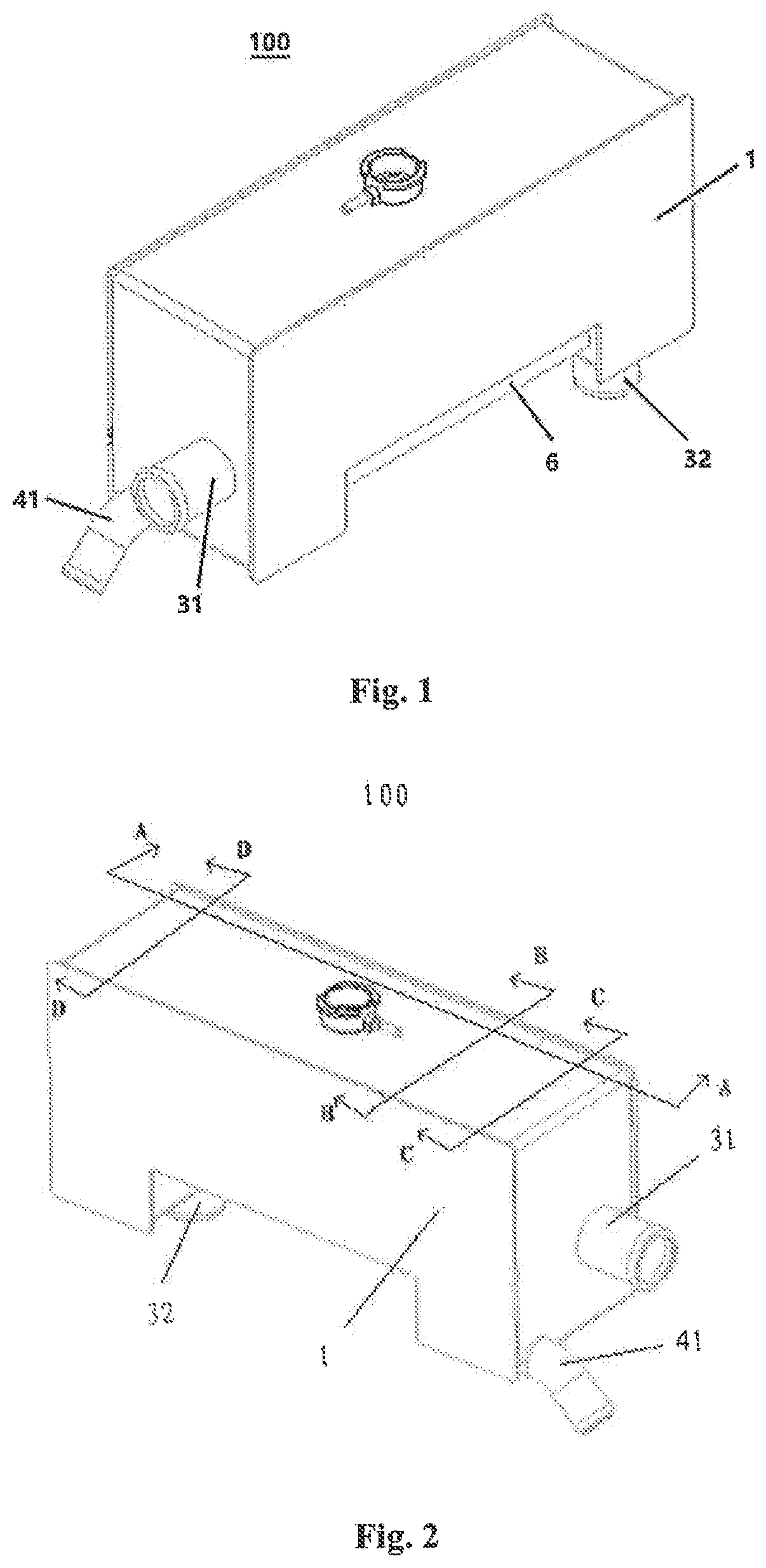
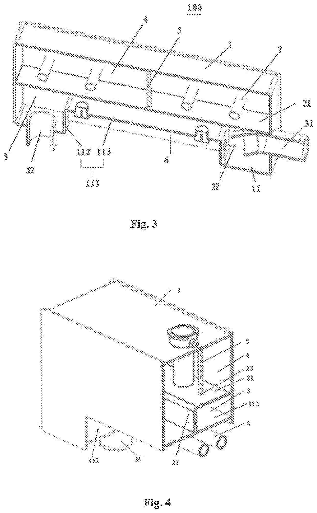
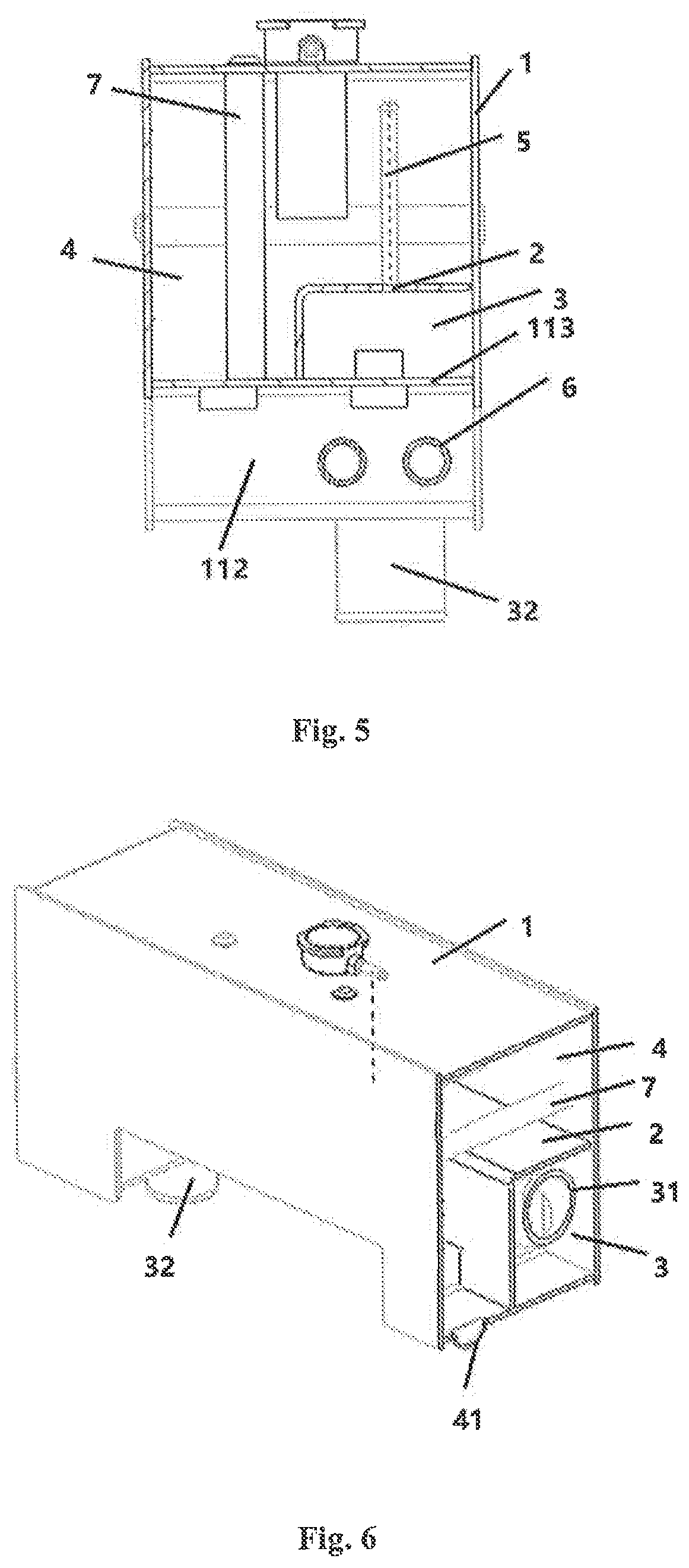
The present invention provides an exhaust tank between the engine and heat exchanger to separate gas from coolant, reducing impact on heat exchanger and promoting better heat transfer. The tank can be integrated into the engine cooling system for easy installation and storage. The tank slows down coolant flow and provides a protrusion to enhance gas separation, while the coolant temperature is reduced by an auxiliary cooling pipe outside the tank, improving heat exchange.

Problems solved by technology

These bubbles are mixed in the coolant to cause thermal stress impact to the cooling pipes of the heat exchanger, resulting in a decrease in heat exchange performance.
In addition, these bubbles may cause a partial vacuum in the engine cooling system, impacting the liquid supply capacity of the pump of the cooling system, so that the heat generated by the engine during operation cannot be fully taken away by the coolant in time and the engine may be overheated.

Method used


Image

  • Tank used in engine cooling system, engine cooling system, and work machine
  • Tank used in engine cooling system, engine cooling system, and work machine
  • Tank used in engine cooling system, engine cooling system, and work machine

Examples


Embodiment Construction

[0024]The technical solutions of the present invention will be further described in detail below in conjunction with the embodiments and the accompanying drawings. The description of the embodiments of the present invention with reference to the accompanying drawings intends to illustrate the general inventive concept of the invention, and should not be construed as a limitation to the invention.

[0025]In addition, in the detailed description below, for ease of interpretation, many specific details are described to provide a comprehensive understanding of the disclosed embodiments. Obviously, however, one or more embodiments may also be implemented without these specific details. In other cases, well-known structures and devices are illustrated schematically to simplify the drawings.

[0026]FIG. 11 shows a schematic principle diagram of an exemplary engine cooling system. Coolant is circulated in the engine cooling system under the action of a pump 300. The coolant is pumped into the e...


PUM


Abstract

The invention relates to a tank used in an engine cooling system, the engine cooling system, and a work machine. The tank includes a housing and a partition which dividing the housing into an exhaust tank and an expansion tank which are sealed from each other. The exhaust tank includes a first connecting pipe and a second connecting pipe, the first connecting pipe being adapted to be fluidly connected to an engine cylinder jacket of the engine cooling system to introduce coolant into the exhaust tank, and the second connecting pipe being adapted to be fluidly connected to a heat exchanger of the engine cooling system to discharge the coolant into the heat exchanger. The expansion tank includes a third connecting pipe adapted to be fluidly connected to the engine cooling system. The tank further includes a guiding tube having a first end in communication with the exhaust tank, and a second end arranged in the expansion tank, so that gas contained in the coolant flowing through the exhaust tank is exported into the expansion tank through the guiding tube. The exhaust tank enables the gas in the coolant to be separated before entering the heat exchanger, and the thermal stress impact to the heat exchanger is reduced.

Description

TECHNICAL FIELD[0001]The present invention relates to a tank used in an engine cooling system, the engine cooling system, and a work machine comprising the tank.BACKGROUND[0002]A work machine is generally provided with an engine cooling system to prevent the engine from overheating, which is particularly important for heavy machinery (such as loaders) where the engine has a high compression ratio and generates a large amount of heat.[0003]A coolant pump is provided in the engine cooling system to drive a coolant to flow through the cooling system. An engine cylinder jacket is provided outside an engine cylinder, and the coolant flows through the engine cylinder jacket under the action of the pump to take away the heat generated by the engine during operation. Thereafter the high-temperature coolant enters into the heat exchanger where it is cooled, then the cooled liquid is again pumped into the engine cylinder jacket by the pump, thus circulation of the cooling system is achieved.[...

Claims


Application Information

Patent Timeline
Patent Type & Authority Applications(United States)
IPC IPC(8): F01P11/02F01P11/04F02F1/16F01P5/10
CPCF01P11/028F01P11/04F01P5/10F02F1/16F01P11/029
Inventor DONG, LITIAN, GUOPING
Owner CATEPILLAR SARL
Why Eureka
Try Eureka