Power transmission device and vehicle including the same

a technology of power transmission device and power transmission device, which is applied in the field of vehicles, can solve the problems of difficult mounting of motor and reducer in the wheel, and achieve the effects of reducing the complexity of the vehicle structure, improving driving performance, and increasing the reduction gear ratio

Active Publication Date: 2022-01-27
HYUNDAI MOBIS CO LTD
View PDF0 Cites 0 Cited by
  • Summary
  • Abstract
  • Description
  • Claims
  • Application Information

AI Technical Summary

Benefits of technology

[0007]Power transmission devices and vehicles having the same constructed according to the principles and exemplary implementations of the invention can provide variable gear reduction in a motor-driven vehicle and significantly reduce the complexity of the vehicle structure compared to the related art, without eliminating advantages achieved by the related art.
[0008]Also, power transmission devices and vehicles having the same constructed according to the principles and exemplary implementations of the invention can increase the reduction gear ratio in a low-speed section of the vehicle to thereby improve driving performance, and reduce the gear reduction ratio when a wheel rotates a motor in a high-speed section of the vehicle to thereby suppress an increase in the rotational speed of a rotating shaft of the motor and effectively protect the motor.

Problems solved by technology

Applicants realized that the narrow interior space of the wheel in the related art makes it difficult for the motor and the reducer to be mounted in the wheel.
In particular, in order to vary the reduction gear ratio of the reducer according to vehicle driving conditions, a separate clutch is required, which has served as a major obstacle to achieving a compact design for the motor-driven vehicle.

Method used


Image

  • Power transmission device and vehicle including the same
  • Power transmission device and vehicle including the same
  • Power transmission device and vehicle including the same

Examples


Embodiment Construction

[0038]The invention is described more fully hereinafter with reference to the accompanying drawings, in which embodiments of the invention are shown. This invention may, however, be embodied in many different forms and should not be construed as limited to the embodiments set forth herein. Rather, these embodiments are provided so that this disclosure is thorough, and will fully convey the scope of the invention to those skilled in the art. Like reference numerals in the drawings denote like elements.

[0039]Hereinafter, a power transmission device and a vehicle including the same constructed according to the principles and exemplary embodiments of the invention will be described in detail with reference to the accompanying drawings.

Power Transmission Device for Vehicle

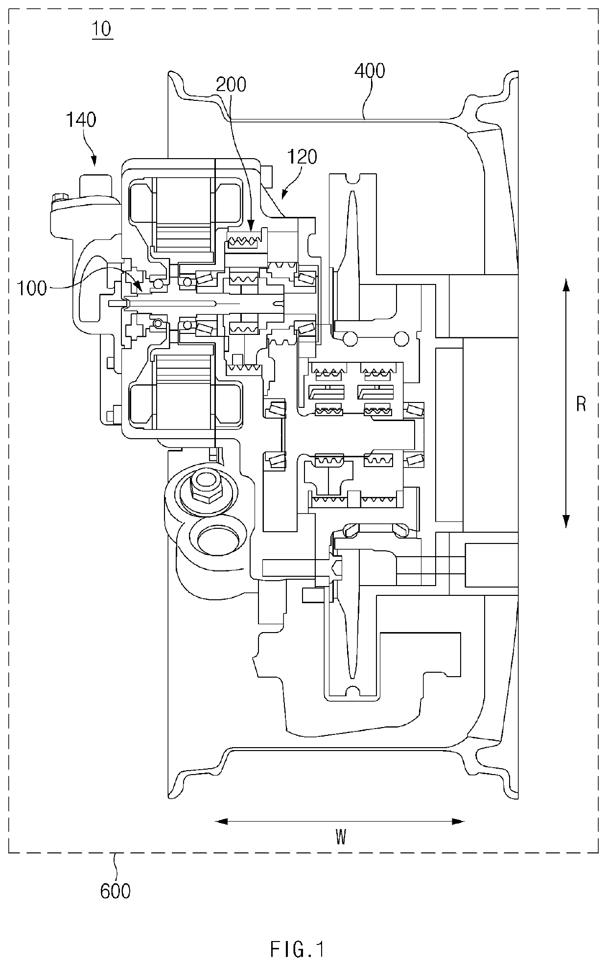
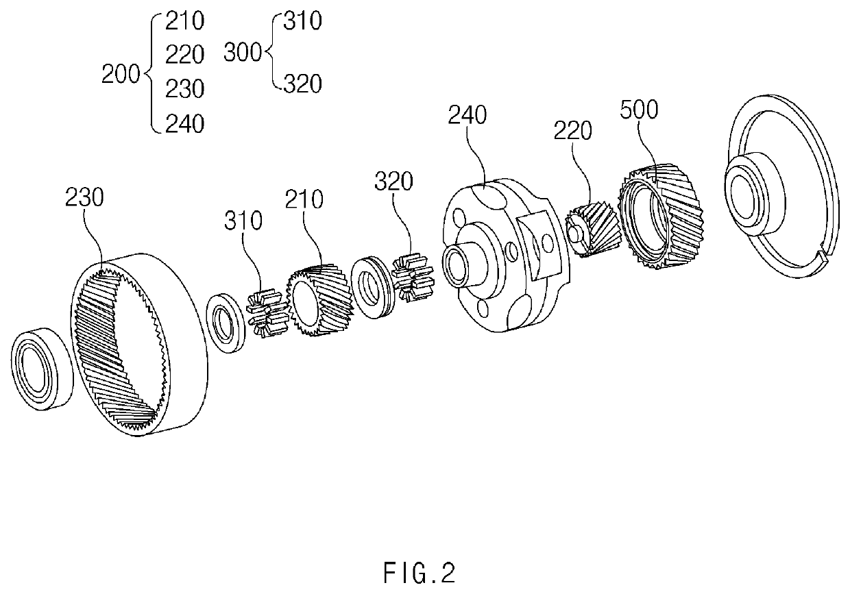
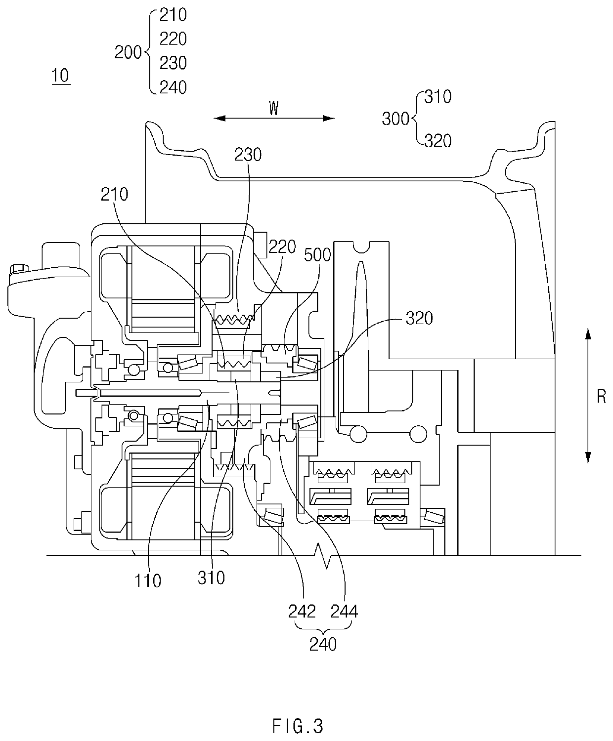
[0040]FIG. 1 is a cross-sectional view of an exemplary embodiment of a power transmission device constructed according to principles of the invention. FIG. 2 is an exploded perspective view of the power transmission dev...


PUM


Abstract

A power train for a vehicle, the power train includes: a motor including a rotatable shaft; a reducer coupled to the motor; a gear train disposed at least partially inside the reducer, to transmit rotational force generated by the motor; and a wheel rotatable by receiving power from the reducer or by transmitting power generated by its rotation to the reducer, wherein the gear train is configured to transmit power from the motor to the reducer or to transmit power from the reducer to the motor based upon comparison of a rotational angular velocity of the rotatable shaft and a rotational angular velocity of the reducer.

Description

CROSS-REFERENCE TO RELATED APPLICATION[0001]This application claims priority from and the benefit of Korean Patent Application No. 10-2020-0093327, filed on Jul. 27, 2020, which is hereby incorporated by reference for all purposes as if set forth herein.BACKGROUNDField[0002]Exemplary embodiments of the invention relate generally vehicles and, more particularly, to a power transmission device for a vehicle.Discussion of the Background[0003]Motors that convert electrical energy into kinetic energy may be applied to various fields and devices and / or apparatuses. For example, the motor may be mounted in a vehicle to produce a vehicle driving force. In particular, as the demand for eco-friendly vehicles to solve environmental pollution problems of existing internal combustion engines is increasing, the demand for motors mounted in the vehicles is also increasing rapidly.[0004]In order to drive the vehicle using the motor, the rotational speed of a rotating shaft provided in the motor sho...

Claims


Application Information

Patent Timeline
Patent Type & Authority Applications(United States)
IPC IPC(8): B60K17/04B60K17/02B60K17/14B60K17/26
CPCB60K17/046B60K17/26B60K17/145B60K17/02F16H3/44F16H57/023F16H57/082B60K17/08F16H2200/0021B60K7/0007B60K2007/0061B60K2007/0038B60K17/043B60Y2400/427B60K2007/0046B60Y2300/18125F16H1/32B60Y2200/91
Inventor SHIN, KYEONG HO
Owner HYUNDAI MOBIS CO LTD
Why Eureka
Try Eureka