Wind turbine blade lightning protection system

a technology of lightning protection system and wind turbine blade, which is applied in the direction of machines/engines, mechanical equipment, and final product manufacturing, etc., can solve the problem that the steel receptor could create high frequency nois

Active Publication Date: 2022-01-06
LM WIND POWER AS
View PDF1 Cites 0 Cited by
  • Summary
  • Abstract
  • Description
  • Claims
  • Application Information

AI Technical Summary

Benefits of technology

[0010]The inventors have found that a lightning receptor comprising graphite may be surprisingly advantageous compared to a receptor formed of metal. For instance, no lightning crater is made in a graphite receptor. This means that it is surprisingly durable and therefore will not change noise characteristics even if struck by lightning. Because no crater is made, there will be no melted metal being thrown off, contaminating the surroundings. When a lightning channel attaches to the graphite receptor, the lightning channel may spread out to completely surround the surface of the receptor. This reduces heat transmission and air pressure raise, putting less stress on the immediate surroundings. It was also found that a crater in stainless-steel receptors could create high frequency noise. In Tungsten receptors, this is less the case as the crater is more rounded.
[0020]The inventive cover member provides a robust way of installing a lightning receptor, especially at the trailing edge in the vicinity of the tip end of a wind turbine blade, where the blade is typically more fragile due to the tip end's relatively small dimensions. This applies to receptors made entirely of graphite, receptors comprising graphite, metallic receptors and other types of receptors.
[0031]The cover member makes it possible to effectively cover openings located for instance near the trailing edge of a wind turbine blade.
[0046]While it is clear from the above that the recess is formed in blade shells, it is also recognized that the blade tip or blade could be manufactured first after which a recess is cut at the trailing edge to expose the end of the down conductor and to arrange the electrical connector. Forming the opening after manufacturing the shell body in fact has the advantage that blade shrinkage has ceased, which might otherwise cause recesses made during manufacturing of the shell body to be misaligned as a result of uneven shrinkage between blade shells.

Problems solved by technology

It was also found that a crater in stainless-steel receptors could create high frequency noise.

Method used


Image

  • Wind turbine blade lightning protection system
  • Wind turbine blade lightning protection system
  • Wind turbine blade lightning protection system

Examples


Embodiment Construction

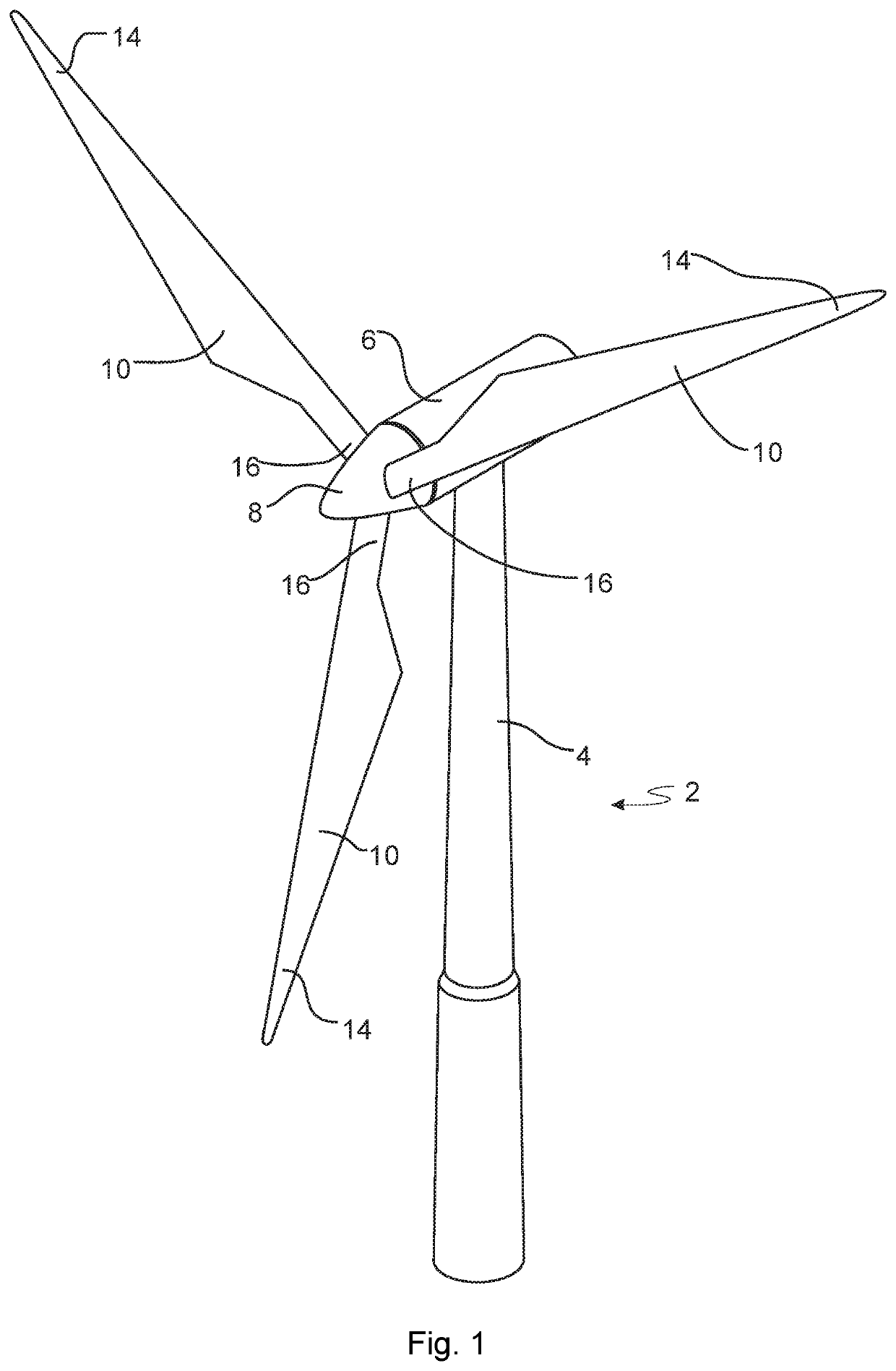
[0056]FIG. 1 illustrates a conventional modern upwind wind turbine 2 according to the so-called “Danish concept” with a tower 4, a nacelle 6 and a rotor with a substantially horizontal rotor shaft. The rotor includes a hub 8, and three blades 10 extending radially from the hub 8, each having a blade root 16 nearest the hub and a blade tip 14 furthest from the hub 8.

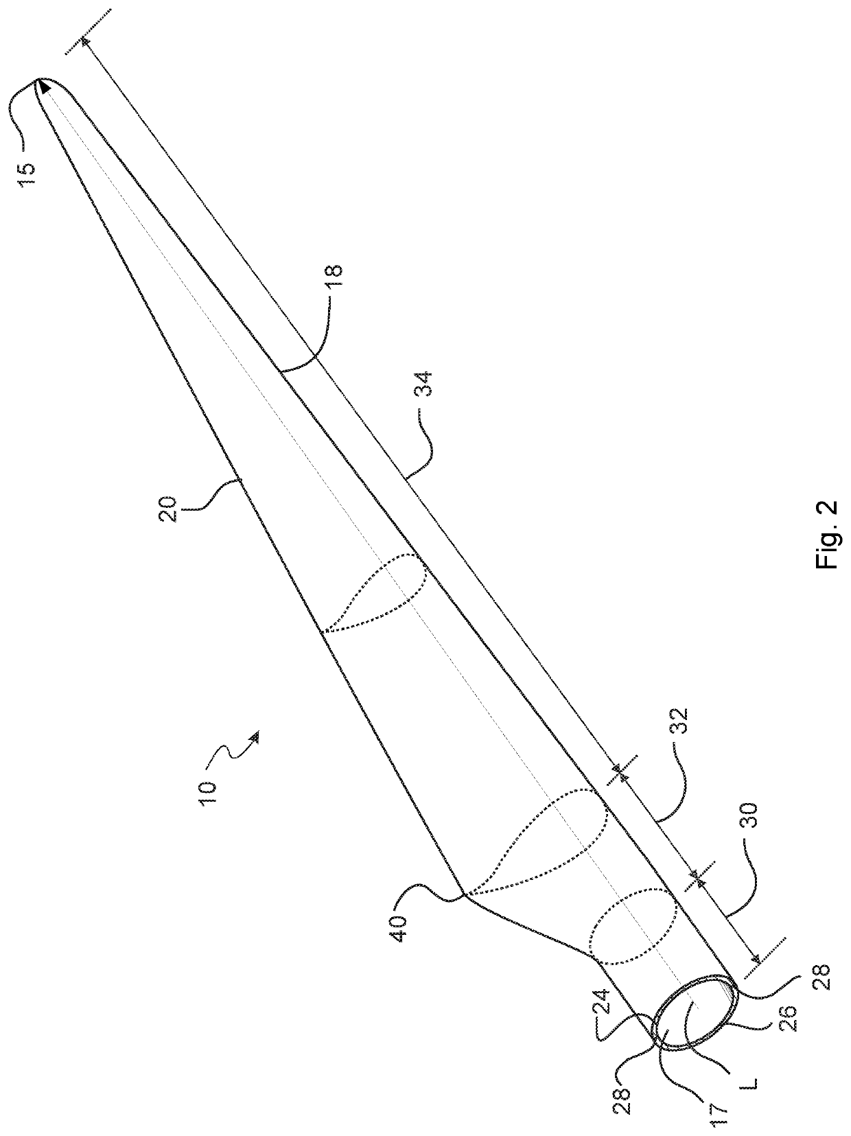
[0057]FIG. 2 shows a schematic view of an exemplary wind turbine blade 10. The wind turbine blade 10 has the shape of a conventional wind turbine blade with a root end 17 and a tip end 15 and comprises a root region 30 closest to the hub, a profiled or an airfoil region 34 furthest away from the hub and a transition region 32 between the root region 30 and the airfoil region 34. The blade 10 comprises a leading edge 18 facing the direction of rotation of the blade 10, when the blade is mounted on the hub, and a trailing edge 20 facing the opposite direction of the leading edge 18.

[0058]The airfoil region 34 (also called t...


PUM


Abstract

Disclosed is a wind turbine blade comprising a shell body, a down conductor arranged in the shell body for conducting lightning current to ground, an electrical connector arranged in electrical connection with the down conductor, a lightning receptor element arranged at a surface of the shell body or outside the shell body, the lightning receptor element being in electrical connection with the electrical connector. A method for manufacturing a wind turbine blade with a lightning protection system is also provided.

Description

[0001]The present disclosure relates to lightning protection of a wind turbine blade.BACKGROUND[0002]As wind turbines and wind turbine blades increase in size, the risk of lighting striking the wind turbine increases. It is therefore of increasing interest to provide wind turbines and in particular wind turbine blades with lightning protection measures.[0003]It is known to provide blades for wind turbines with lightning receptors that, inside the blade, are in electric connection with a metallic down conductor that is able to connect a lightning current to earth.[0004]Wind turbine blades of fibre-reinforced polymer and in particular the aerodynamic shells of wind turbine blades are usually manufactured in moulds, where the pressure side and the suction side of the blade are manufactured separately by arranging glass fibre mats and / or other fibre-reinforcement material, such as carbon fibre, in each of the two mould parts. Afterwards, the two halves are positioned on top of each othe...

Claims


Application Information

Patent Timeline
Patent Type & Authority Applications(United States)
IPC IPC(8): F03D80/30F03D1/06
CPCF03D80/30F05B2230/60F03D1/0675Y02E10/72Y02P70/50F05B2240/304
Inventor HANSEN, LARS BOAUBRION, MATHILDEELKJAER-HOLM, CHRISTIANVEERAPPA, MADHUSUDHAN NANJEDEVANAPURA
Owner LM WIND POWER AS
Why Eureka
Try Eureka