
Light guide film, production method thereof and light guide device

a technology of light guide film and production method, which is applied in the direction of optical light guide, instruments, optics, etc., can solve the problems of high manufacturing cost and precise light guide plate, waste of whole light guide plate once damaged, and unfavorable long-term use, etc., to achieve convenient cleaning, improve light emitting effect, and easy to clean dirt.

Pending Publication Date: 2021-12-23
HANGZHOU XINENG NEW MATERIAL CO LTD
View PDF8 Cites 0 Cited by
  • Summary
  • Abstract
  • Description
  • Claims
  • Application Information

AI Technical Summary

Benefits of technology

The patent text describes a new light guide film, a method of producing it, and a light guide device that can improve the bonding between the film and the substrate, while protecting the ultrastructure without affecting the light guiding effect. The technical effects include better and more reliable bonding, improved protection of the ultrastructure, and unobstructed light guiding.

Problems solved by technology

The light guide plate is high in manufacturing cost and precise in optical structure, and the whole light guide plate needs to be wasted once being damaged.
However, the above-mentioned solution has certain drawbacks, because the transparent film and the transparent substrate are separately arranged, the firmness of the bonding between the transparent film and the transparent substrate should be considered when the transparent film and the transparent substrate are bonded.
Although there are a lot of light guide points, the transparent film and the transparent substrate are not made of the same material, and the point-to-surface bonding is easy to separate, which is not beneficial for long-term use.
Compared with the prior art, the lower surface of the light guide film is smoothly arranged, so that when the lower surface of the light guide film is fixed with the substrate, the whole surface can be bonded, the contact area is maximized, the fixing effect can also be optimized, and the light guide film and the substrate are not easy to separate.
Furthermore, the ultrastructure of the light guide is arranged inside the light guide film, so that the ultrastructure for light guide is not easy to damage and has stronger stretch-resistant capability.
Since the ultrastructure is disposed inside the light guide film, it is difficult to form at a time through a single mold.
The precision of the ultrastructure is too high.
If the upper die and the lower die each has a part of the ultrastructure, the precise bonding cannot be ensured when the last two parts of the finished product are bonded, the ultrastructure is easily displaced, which affects the light guiding effect.
By adopting the above technical solution, the light guide film can be formed at a time through a single mold, the process is simpler, the molding effect is better, and the light guide film is not easily deformed.
By adopting the above technical solution, since the lower surface of the light guide film is a smoothly transitioned flat surface, so that when the light guide film is fixed to the substrate, the whole surface can be attached, the contact area reaches the maximum, the fixing effect can be optimized, and the light guide film and the substrate are not easy to separate.
Meanwhile, the ultrastructure is arranged inside the light guide film, so that light can be guided, the ultrastructure is not easy to damage and has stronger stretch-resistant capability.

Method used


Image

  • Light guide film, production method thereof and light guide device
  • Light guide film, production method thereof and light guide device
  • Light guide film, production method thereof and light guide device

Examples


embodiment 1

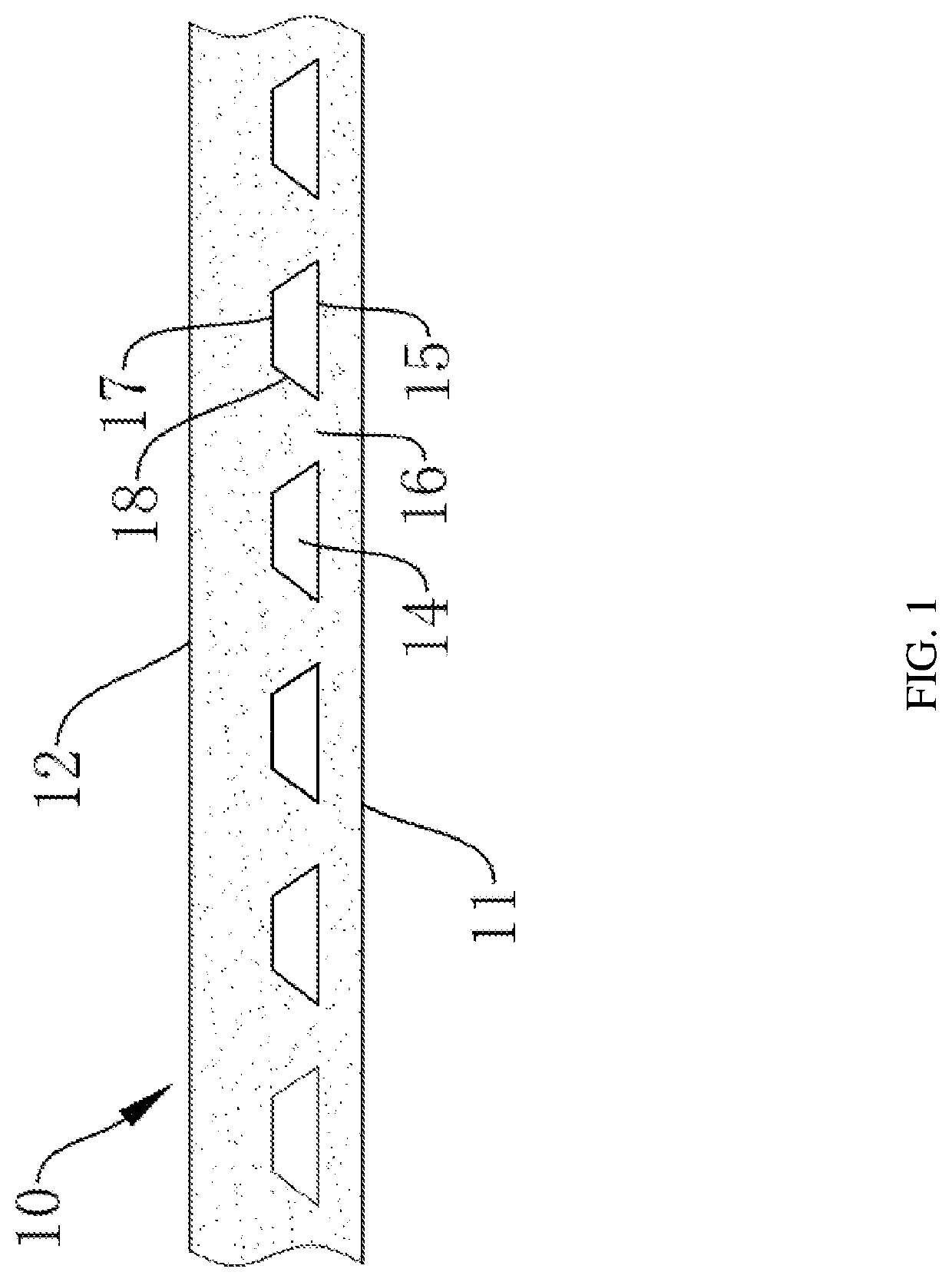
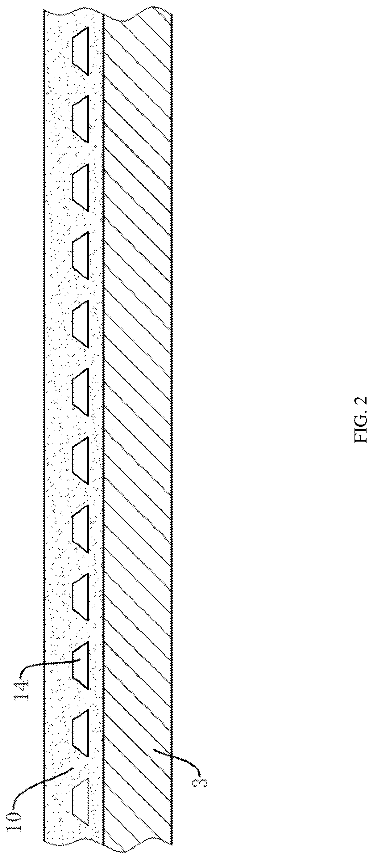
[0052]Referring to FIG. 1, a light guide film 10 is provided, an upper surface of the light guide film 10 is a light exit surface 12, and a lower surface of the light guide film 10 is a light incident surface 11. The lower surface of the light guide film 10 is smooth and is used for being fixedly connected with the substrate 3 (see FIG. 2). A plurality of hollow ultrastructures 14 are disposed in the light guide film 10, and a side of the hollow ultrastructures 14 close to the lower surface of the light guide film 10 is a conduction reflecting surface 15, and a gap between every two adjacent ultrastructures 14 is a light exit gap 16.

[0053]In this embodiment, the lower surface of the light guide film 10 is arranged to be smooth, so that when the light guide film 10 is fixed to the substrate 3, the whole surface can be attached, the contact area reaches the maximum, the fixing effect can be optimized, and the light guide film 10 and the substrate 3 are not easy to separate.

[0054]In th...

embodiment 2

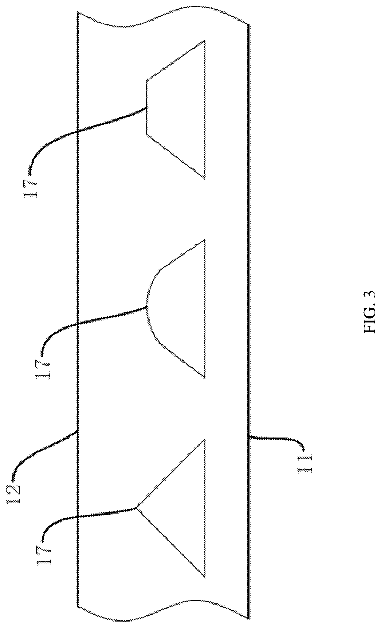
[0068]This embodiment differs from Embodiment 1 in that, in this embodiment, the light exit reflecting surface 18 is a cambered surface.

[0069]Referring to FIG. 8, it is shown a light emitting path when the light exit reflecting surface 18 is an inclined surface in Embodiment 1. When light rays are irradiated on the inclined surface, the light rays are reflected and then irradiated on the light exit surface 12, and since the angles of the light irradiated on the inclined surface are different, the angles of the light irradiated on the light exit surface 12 after being reflected are also different, and the intensity of the light emitted is different.

[0070]In this embodiment, as shown in FIG. 9, the light exit reflecting surface 18 is arranged as a cambered surface. When the light exit reflecting surface is a curved surface, the included angle between a tangent plane at any point on the curved surface and the light incident surface is 45° to 85°. The angle of the cambered surface is de...

embodiment 3

[0072]This embodiment provides a production process of a hollow ultrastructure light guide film, which is used for producing the light guide film of Embodiment 1, and the production process includes the following steps of:

[0073]1) selecting raw materials, in which the raw materials of the light guide film are optical quality transparent silica gel;

[0074]2) selecting a mold (with an ultrastructure core mold) conforming with the light guide film;

[0075]3) injecting silica gel raw materials into the mold, and molding same by a silica gel molding process.

[0076]An integrally formed light guide film, the process is simpler, and the hollow ultrastructure is arranged inside the light guide film, and is not easily damaged by itself and has a stronger stretch-resistant capability while guiding light.


PUM

PropertyMeasurementUnit
included angleaaaaaaaaaa
distanceaaaaaaaaaa

Abstract

The application relates to a light guide film, a production method thereof and a light guide device. An upper surface of the light guide film is a light exit surface and a lower surface is a light incident surface; the lower surface of the light guide film is smooth and is used for being connected with the substrate; a plurality of hollow ultrastructures are disposed in the light guide film, the hollow ultrastructure close to the lower surface of the light guide film is a conduction reflecting surface, and a gap between every two adjacent ultrastructures is a light exit gap.

Description

CROSS-REFERENCE TO RELATED APPLICATION[0001]This application is a continuation of international application of PCT application No. PCT / CN2021 / 073199 filed on Jan. 22, 2021, which claims the priority benefit of China application No. 202010213902.9 filed on Mar. 24, 2020. The entirety of each of the above-mentioned patent applications is hereby incorporated by reference herein and made a part of this specification.BACKGROUNDTechnical Field[0002]The application relates to the field of light guide materials, and more particularly, to a light guide film, a production method thereof and a light guide device.Description of Related Art[0003]A light guide structure is commonly found in a light guide plate, and the light guide plate is a high-tech product for converting a linear light source into a surface light source. Light guide spots are printed on the bottom surface of an optical-grade acrylic / PC plate by using an engraving printing technology. The light emitted from the light source is ...

Claims


Application Information

Patent Timeline
Patent Type & Authority Applications(United States)
IPC IPC(8): F21V8/00
CPCG02B6/0053G02B6/0065G02B6/0015G02B6/0028G02B6/0041G02B6/0055G02B6/0061
Inventor SHE, XIAOFENGHU, KEQING
Owner HANGZHOU XINENG NEW MATERIAL CO LTD
Learn More