Broadband panel array antenna

a panel array and antenna technology, applied in the field of panel array antennas, can solve the problems of increasing spectrum resources, large overall size of feed antennas, and crowded lower microwave frequency bands, and achieve the effects of reducing return losses, broadening the dominant-mode bandwidth, and good broadband transmission properties

Active Publication Date: 2021-11-18
NINGBO UNIV
View PDF8 Cites 2 Cited by
  • Summary
  • Abstract
  • Description
  • Claims
  • Application Information

AI Technical Summary

Benefits of technology

[0011]The E-plane rectangular waveguide-single ridge converter includes a first rectangular metal block, wherein a rectangular port and a fifth rectangular cavity are formed in the first rectangular metal block, the rectangular port is the input terminal of the E-plane rectangular waveguide-single ridge converter, the upper end face of the rectangular port is a certain distance away from the upper end face of the first rectangular metal block, the front end face of the rectangular port is located on the same plane as the front end face of the first rectangular metal block, the upper end face of the fifth rectangular cavity is located on the same plane as the upper end face of the first rectangular metal block, the right end face of the fifth rectangular cavity is located on the same plane as the right end face of the rectangular port, the front end face of the fifth rectangular cavity is connected and attached to the rear end face of the rectangular port, the lower end face of the fifth rectangular cavity is located on the same plane as the lower end face of the rectangular port, a plane where the left end face of the rectangular port is located is a certain distance away from a plane where the left end face of the fifth rectangular cavity is located, the left end face of the fifth rectangular cavity is a certain distance away from the left end face of the first rectangular metal block, the distance from the left end face of the fifth rectangular cavity to the left end face of the first rectangular metal block is equal to the distance from the right end face of the fifth rectangular cavity to the right end face of the first rectangular metal block, the lower end face of the fifth rectangular cavity is a certain distance away from the lower end face of the first rectangular metal block, a single-ridge step, an E-plane step and an H-plane step are disposed in the fifth rectangular cavity and are all rectangular blocks, the right end face of the H-plane step is connected and attached to the right end face of the fifth rectangular cavity, the lower end face of the H-plane step is connected and attached to the lower end face of the fifth rectangular cavity, the left end face of the H-plane step is connected and attached to the right end face of the single-ridge step, the lower end face of the single-ridge step is connected and attached to the lower end face of the fifth rectangular cavity, the upper end face of the single-ridge step is located on the same plane as the upper end face of the fifth rectangular cavity, the left end face of the single-ridge step is connected and attached to the right end face of the E-plane step, the left end face of the E-plane step is connected and attached to the left end face of the fifth rectangular cavity, and the lower end face of the E-plane step is connected and attached to the lower end face of the fifth rectangular cavity; the front-back length of the H-plane step is half that of the fifth rectangular cavity, the left-right length of the H-plane step is one third that of the fifth rectangular cavity, the vertical length of the H-plane step is two fifths that of the fifth rectangular cavity, the front-back length of the single-ridge step is half that of the fifth rectangular cavity, the left-right length of the single-ridge step is one third that of the fifth rectangular cavity, the vertical length of the single-ridge step is equal to that of the fifth rectangular cavity, the front-back length of the E-plane step is equal to that of the fifth rectangular cavity, the left-right length of the E-plane step is one third that of the fifth rectangular cavity, the vertical length of the E-plane step is a quarter that of the fifth rectangular cavity, and the upper end face of the fifth rectangular cavity is the output terminal of the E-plane rectangular waveguide-single ridge converter; the first-stage H-type E-plane waveguide power divider includes a first rectangular block, a second rectangular block, a third rectangular block, a first matching block, a second matching block and a fourth rectangular block, wherein the upper end face of the first rectangular block, the upper end face of the second rectangular block, the upper end face of the third rectangular block, the upper end face of the first matching block, the upper end face of the second matching block and the upper end face of the fourth matching block are located on the same plane, the left end face of the first rectangular block is parallel to the left end face of the second panel, the front-back length of the first rectangular block is 0.7λ, the left-right length of the first rectangular block is 0.125λ, the vertical length of the first rectangular block is 0.8λ, the left end face of the third rectangular block is connected and attached to the right end face of the first rectangular block, the front-back length of the third rectangular block is 0.125λ, the left-right length of the third rectangular block is 0.9λ, the vertical length of the third rectangular block is 0.8λ, the distance from a plane where the front end face of the third rectangular block is located to a plane where the front end face of the first rectangular block is located is equal to the distance from a plane where the rear end face of the third rectangular block is located to a plane where the rear end face of the first rectangular block is located, the right end face of the third rectangular block is connected and attached to the left end face of the second rectangular block, the front-back length of the second rectangular block is 0.7λ, the left-right length of the second rectangular block is 0.125λ, the vertical length of the second rectangular block is 0.8λ, the distance from a plane where the front end face of the third rectangular block is located to a plane where the front end face of the second rectangular block is located is equal to the distance from a plane where the rear end face of the third rectangular block is located to a plane where the rear end face of the second rectangular block is located, the first matching block is a rectangular block, the left end face of the first matching block is connected and attached to the right end face of the first rectangular block, the rear end face of the first matching block is connected and attached to the front end face of the third rectangular block, the front-back length of the first matching block is one-tenth that of the first rectangular block, the left-right length of the first matching block is four fifths that of the first rectangular block, the vertical length of the first matching block is 0.8λ, the second matching block and the first matching block are symmetrical left and right with respect to a front-back midline of the third rectangular block, the front end face of the fourth rectangular block is connected and attached to the rear end face of the third rectangular block, the distance from the left end face of the fourth rectangular block to the right end face of the first rectangular block is equal to the distance from the right end face of the fourth rectangular block to the left end face of the second rectangular block, the left-right length of the fourth rectangular block is 1.25 times that of the first rectangular block, the vertical length of the fourth rectangular block is 0.8λ, and the front end face of the first rectangular block, the rear end face of the first rectangular block, the front end face of the second rectangular block and the rear end face of the second rectangular block are used as the four output terminals of the first-stage H-type E-plane waveguide power divider respectively; the second-stage H-type E-plane waveguide power divider includes a fifth rectangular block, a sixth rectangular block, a seventh rectangular block, an eighth rectangular block, a first conversion block, a second conversion block, a third conversion block and a fourth conversion block, wherein the upper end face of the fifth rectangular block, the upper end face of the sixth rectangular block, the upper end face of the seventh rectangular block, the upper end face of the first conversion block, the upper end face of the second conversion block, the upper end face of the third conversion block, the upper end face of the fourth conversion block and the upper end face of the eighth rectangular block are located on the same plane, the front-back length of the fifth rectangular block is 1.2λ, the left-right length of the fifth rectangular block is 0.125λ, the vertical length of the fifth rectangular block is 0.8λ, a first rectangular recess is formed in the left end face of the fifth rectangular block, the vertical length of the first rectangular recess is equal to that of the fifth rectangular block, the front-back length of the first rectangular recess is smaller than that of the fifth rectangular cavity, the left-right length of the first rectangular recess is smaller than that of the fifth rectangular cavity, the distance from a plane where the front end face of the first rectangular recess is located to a plane where the front end face of the fifth rectangular block is located is equal to the distance from a plane where the rear end face of the first rectangular recess to a plane where the rear end face of the fifth rectangular block is located, the sixth rectangular block and the fifth rectangular block are symmetrical left and right, the center distance between the sixth rectangular block and the fifth rectangular block is 1.9λ, the left end face of the seventh rectangular block is connected and attached to the right end face of the fifth rectangular block, the right end face of the seventh rectangular block is connected and attached to the left end face of the sixth rectangular block, the front-back length of the seventh rectangular block is 0.2λ, the left-right length of the seventh rectangular block is 1.9λ, the vertical length of the seventh rectangular block is 0.8λ, the distance from a plane where the front end face of the seventh rectangular block is located to a plane where the front end face of the fifth rectangular block is located is equal to the distance from a plane where the rear end face of the seventh rectangular block is located to a plane where the rear end face of the fifth rectangular block is located, a stepped recess is formed in the front end face of the seventh rectangular cavity and includes a second rectangular recess and a third rectangular recess which are communicated with each other, the vertical length of the second rectangular recess and the third rectangular recess is equal to that of the seventh rectangular block, the left-right length of the second rectangular recess is smaller than that of the third rectangular recess, the left-right length of the third rectangular recess is smaller than that of the seventh rectangular block, the front-back length of the second rectangular recess is smaller than that of the third rectangular recess, the sum of the front-back length of the second rectangular recess and the front-back length of the third rectangular recess is smaller than the front-back length of the seventh rectangular block, the front end face of the third rectangular recess is located on the same plane as the front end face of the seventh rectangular block, the rear end face of the third rectangular recess is connected and attached to the front end face of the second rectangular recess, the distance from the left end face of the third rectangular recess to the left end face of the seventh rectangular block is equal to the distance from the right end face of the third rectangular recess to the right end face of the seventh rectangular block, and the distance from the left end face of the second rectangular recess to the left end face of the seventh rectangular block is equal to the distance from the right end face of the second rectangular recess to the right end face of the seventh rectangular block; the left-right length of the eighth rectangular block is 1.1 times that of the fifth rectangular block, the front end face of the eighth rectangular block is connected and attached to the rear end face of the seventh rectangular block, the distance from the left end face of the eighth rectangular block to the right end face of the fifth rectangular block is equal to the distance from the right end face of the eighth rectangular block to the left end face of the sixth rectangular block, the vertical length of the eighth rectangular block is 0.8λ, the front-back length of the eighth rectangular block is 0.2λ, the left-right length of the eighth rectangular block is 0.2λ, and the rear end face of the eighth rectangular block is the input terminal of the second-stage H-type E-plane waveguide power divider; the first conversion block consists of a ninth rectangular block, a first right-angle triangular block, a second right-angle triangular block and a parallelogram block, wherein the ninth rectangular block, the first right-angle triangular block, the second right-angle triangular block and the parallelogram block are located on the same plane, the front end face of the ninth rectangular block is the front end face of the first conversion block, the left-right length of the ninth rectangular block is equal to 0.2λ, the vertical length of the ninth rectangular block is equal to 0.8λ, the end face where a first right-angle side of the first right-angle triangular block is located is connected and attached to the rear end face of the ninth rectangular block, the length of the end face where the first right-angle side of the first right-angle triangular block is located is equal to the left-right length of the ninth rectangular block, the end face, where a second right-angle side of the first right-angle triangular block is located, is located on the same plane as the left end face of the ninth rectangular block, the vertical length of the first right-angle triangular block is equal to that of the ninth rectangular block, the end face where a first right-angle side of the second right-angle triangular block is located is connected and attached to the front end face of the fifth rectangular block, the end face, where a second right-angle side of the second right-angle triangular block is located, is located on the same plane as the right end face of the fifth rectangular block, the length of the end face where the first right-angle side of the second right-angle triangular block is located is equal to the left-right length of the fifth rectangular block, the vertical length of the second right-angle triangular block is equal to that of the fifth rectangular block, the front end face of the parallelogram block completely overlaps with the end face where a hypotenuse of the second right-angle second triangular block is located, the distance between the front end face and the rear end face of the parallelogram block is 0.2λ, the vertical length of the parallelogram block is equal to that of the second right-angle triangular block, an angle between the end face where the first right-angle side of the first right-angle triangular block is located and the end face where a hypotenuse of the first right-angle second triangular block is located is 22.5°, and an angle between the end face where the first right-angle side of the second right-angle triangular block is located and the end face where the hypotenuse of the second right-angle second triangular block is located is 22.5°; the second conversion block and the first conversion block are symmetrical left and right, the third conversion block overlaps with the second conversion block after being moved rightward by 1.9λ, the third conversion block and the first conversion block are symmetrical front and back, the center distance between the third conversion block and the first conversion block is 1.2λ, the fourth conversion block and the second conversion block are symmetrical front and back, and the front end face of the first conversion block, the front end face of the second conversion block, the front end face of the third conversion block and the front end face of the fourth conversion block are used as the four output terminals of the second-stage H-type E-plane waveguide power divider; the hth-stage H-type E-plane waveguide power divider is identical in structure with the second-stage H-type E-plane waveguide power divider, but the size is increased gradually, and h=3, 4, . . . , k-1; when the four output terminals of each first-stage H-type E-plane waveguide power divider are connected to the input terminals of four E-plane rectangular waveguide-single ridge waveguide converters in a one-to-one corresponding manner, each output terminal of the first-stage H-type E-plane waveguide power divider is attached to and completely overlaps with the input terminal of one E-plane rectangular waveguide-single ridge waveguide converter; when the four output terminals of each second-stage H-type E-plane waveguide power divider are connected to the input terminals of four first-stage H-type E-plane waveguide power dividers in a one-to-one corresponding manner, each output terminal of the second-stage H-type E-plane waveguide power divider is attached to and completely overlaps with the input terminal of one first-stage H-type E-plane waveguide power divider; and when the four output terminals of the hth-stage H-type E-plane waveguide power divider are connected to the input terminals of four (h-1)th-stage H-type E-plane waveguide power dividers in a one-to-one corresponding manner, each output terminal of the hth-stage H-type E-plane waveguide power divider is attached to and completely overlaps with the input terminal of one (h-1)th-stage H-type E-plane waveguide power divider. In the structure, the single-ridge steps, the H-plane steps and the E-plane steps arranged in the E-plane rectangular waveguide-single ridge waveguide converters realize impedance matching, reduce the return loss caused by the discontinuity of the structure, so that the panel array antenna has good broadband transmission properties and can uniformly feed power to the radiating units in the radiating layer and broaden the dominant-mode bandwidth, and ultra-wideband and high-efficiency feed of the array antenna is realized.
[0012]Compared with the prior art, the invention has the following advantages: the polarization layer is additionally disposed over the radiating layer and enables the polarization direction of the electric field generated by the radiating layer to rotate to reduce the side lobe in the E-plane direction diagram and the H-plane direction diagram is reduced to realize a low side lobe; in addition, a multi-stage radiating structure of traditional panel antennas is optimized into one radiating layer, so that the profile height of the panel antenna is greatly reduced under the condition that a broadband structure is realized, machining and assembly requirements are effectively reduced, high assembly precision can be realized more easily, and the low-profile and small-sized design reduces the loss of an interlayer coupling structure of the traditional panel antennas and significantly improves the gain and aperture efficiency of the antenna, so the broadband panel array antenna is low in side lobe, high in gain and efficiency, and low in machining cost.

Problems solved by technology

With the increase of the communication data size in unit time in the modern information society, the shortage of spectrum resources is becoming ever serious, and the lower side of the microwave frequency band has become very crowded.
However, the focal-diameter ratio should be considered to improve the overall efficiency of the feed antennas, which makes the overall size of the feed antennas large and makes it difficult to guarantee a low profile.
However, the decrease of the side lobe of the existing panel array antennas may widen the main lobe and reduce the gain, which makes is impossible to gain an extremely low side lobe under the precondition that a narrow main lobe is guaranteed and the gain is not compromised.
In addition, traditional panel array antennas have high requirements for the welding precision of the feed network layer and the plurality of radiating layer, which results in high machining costs and limits their production and application.

Method used


Image

  • Broadband panel array antenna
  • Broadband panel array antenna
  • Broadband panel array antenna

Examples


Embodiment Construction

[0025]The invention will be described in further detail below in conjunction with the accompanying drawings.

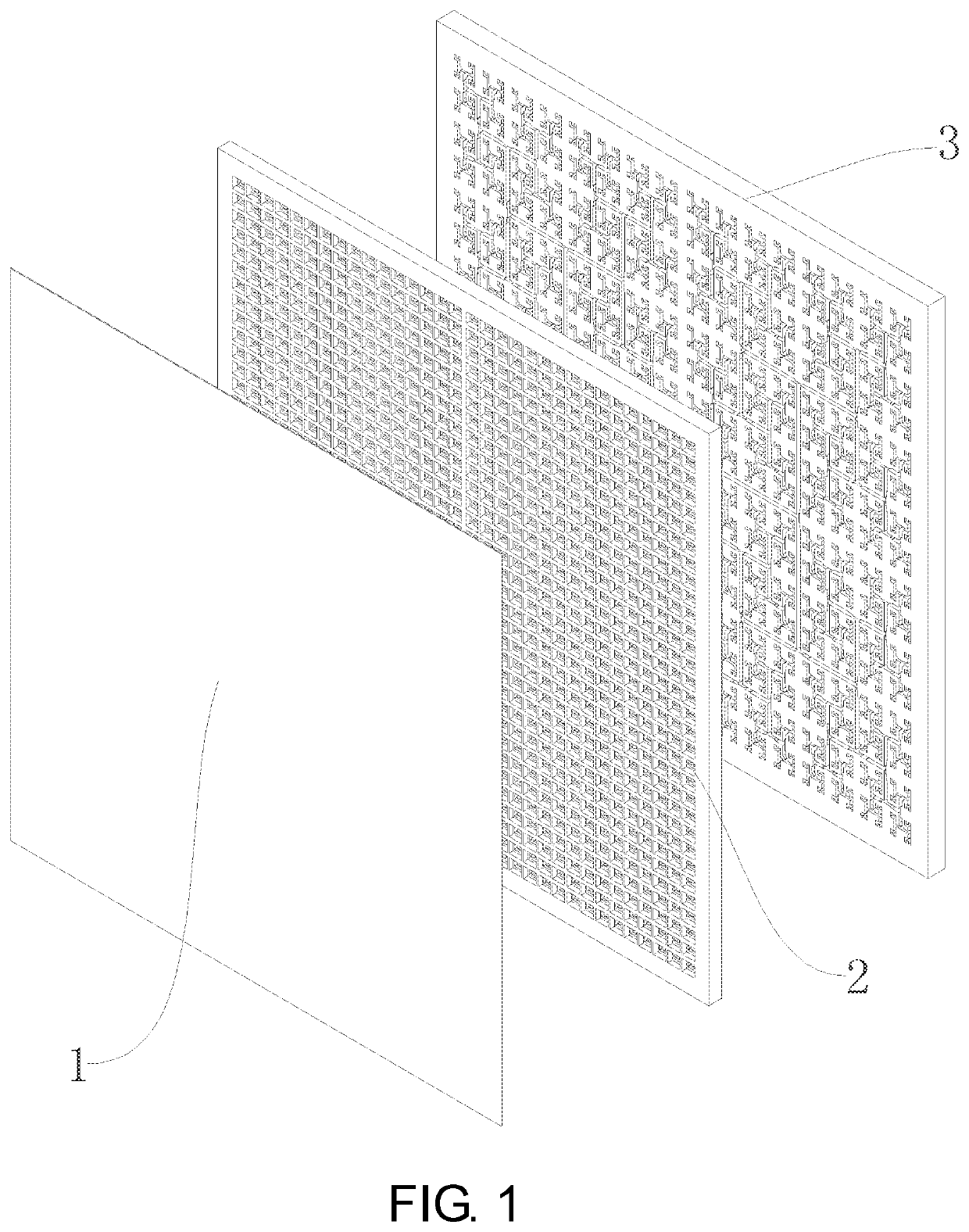
[0026]Embodiment: As shown in FIG. 1, a broadband panel array antenna includes a polarization layer 1, a radiating layer 2 and a feed layer 3 which are sequentially stacked from top to bottom; the feed layer 3 is used for converting a single path of TE10 mode signals into a plurality of paths of same-power in-phase TE10 mode signals and transmitting the plurality of paths of TE10 mode signals to the radiating layer 2, the radiating layer 2 is used for radiating the plurality of paths of TE10 mode signals from the feed layer 3 to a free space, and the polarization layer 1 is used for rotating the polarization direction of an electric field generated by the radiating layer 2 to reduce the side lobe in an E-plane direction diagram and an H-plane direction diagram.

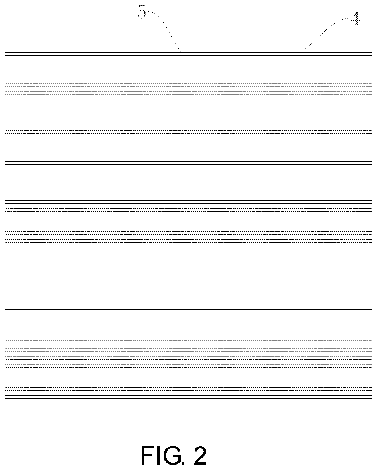
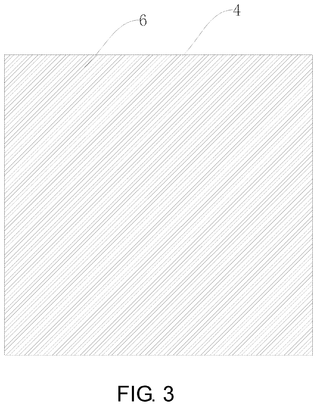
[0027]In this embodiment, as shown in FIG. 2 and FIG. 3, the polarization layer 1 includes a dielectric substrate 4, a...


PUM


Abstract

A broadband panel array antenna includes a polarization layer, a radiating layer and a feed layer which are sequentially stacked from top to bottom. The feed layer is used for converting a single path of TE10 mode signals into a plurality of paths of same-power in-phase TE10 mode signals and transmitting the plurality of paths of TE10 mode signals to the radiating layer. The radiating layer is used for radiating the plurality of paths of TE10 mode signals from the feed layer to a free space. The polarization layer is used for rotating the polarization direction of an electric field generated by the radiating layer to reduce the side lobe in an E-plane direction diagram and an H-plane direction diagram. The broadband panel array antenna has the advantages of being low in side lobe, high in gain and efficiency, and low in machining cost.

Description

CROSS-REFERENCE TO RELATED APPLICATION[0001]This application claims the priority benefit of China application serial no. 202010417843.7, filed on May 18, 2020. The entirety of the above-mentioned patent application is hereby incorporated by reference herein and made a part of this specification.BACKGROUNDTechnical Field[0002]The invention relates to a panel array antenna, in particular to broadband panel array antenna.Description of Related Art[0003]With the increase of the communication data size in unit time in the modern information society, the shortage of spectrum resources is becoming ever serious, and the lower side of the microwave frequency band has become very crowded. The MMW band has a pure electromagnetic environment and available broadband spectrum resources, thus having become the optimal choice of high-rate mobile communication systems. As a frequency band near 80 GHz, E-Band has two symmetrical frequency bands 71-76 GHz and 81-86 GHz, possesses a total bandwidth up ...

Claims


Application Information

Patent Timeline
Patent Type & Authority Applications(United States)
IPC IPC(8): H01Q21/06H01Q21/00H01Q13/26H01Q9/04H01Q1/42
CPCH01Q21/064H01Q21/0087H01Q13/26H01Q1/422H01Q21/005H01Q21/0068H01Q9/045H01Q21/061H01Q1/36H01Q1/38H01Q1/50H01P5/181H01P5/082H01Q15/246H01Q21/0006
Inventor YOU, YANGHUANG, JIFUZHANG, LINGYOU, QINGCHUNLU, YUNLONG
Owner NINGBO UNIV
Why Eureka
Try Eureka