Low-sidelobe plate array antenna

Active Publication Date: 2021-11-18
NINGBO UNIV
View PDF0 Cites 1 Cited by
  • Summary
  • Abstract
  • Description
  • Claims
  • Application Information

AI Technical Summary

Benefits of technology

The invention provides a low-sidelobe plate array antenna that has a wide frequency bandwidth and high efficiency. The antenna has a simple structure, low cost, and is suitable for mass production. The technical effects of the invention include a low sidelobe, compact structure, and ultra-wideband and high-efficiency feeding of the plate antenna. The antenna uses a H-type E-plane waveguide power divider and a three-layer coupled structure to optimize a multi-level radiation structure of traditional plate antennas into a one-level radiation structure. The design restrains cross polarization, improves the gain and aperture efficiency of the plate antennas, and reduces the sidelobe.

Problems solved by technology

However, when the frequency or antenna array size increases, the insertion loss will be increased due to conductor losses and dielectric losses of the micro-strip array antennas.
Thus, the micro-strip array antennas can fulfill a wide band, but cannot fulfill high frequency, high efficiency or high gain.
However, the beam direction of the waveguide slot traveling wave array antennas varies with the frequency, which results in inconsistent directions of antenna beams within a wideband range, and the waveguide slot traveling wave array antennas can only be used within an extremely narrow bandwidth, and the frequency band cannot be expanded.
According to the first solution, the power distribution proportion of the feed layer is controlled to adjust the energy distribution of the radiation layer to reduce the sidelobe; however, when this solution is used to reduce the sidelobe, the main lobe will become wider, the gain will be decreased, and it is impossible to gain an extremely low sidelobe under the condition where a narrow main lobe is guaranteed and the gain is not sacrificed.
However, due to the addition of the polarization layer, the cost of the antennas may be increased by 20% during mass production.
This waveguide slot array antenna has a wide band, a high gain and a low sidelobe, but has the following problems: 1, the radiation layer has too many structure layers which cannot be processed one by one, the assembly structure is complicated, so that mass production is unavailable; 2, the radiation layer adopts a coupling cavity divided into four parts, so that the relative bandwidth is narrow, and a wider frequency bandwidth cannot be obtained; 3, the low-sidelobe property is realized by means of repeated rotation of the several radiation units in the radiation layer, so that the efficiency of the antennas is reduced.

Method used


Image

  • Low-sidelobe plate array antenna
  • Low-sidelobe plate array antenna
  • Low-sidelobe plate array antenna

Examples


Embodiment Construction

[0051]The invention will be further expounded below in conjunction with the accompanying drawings and embodiments.

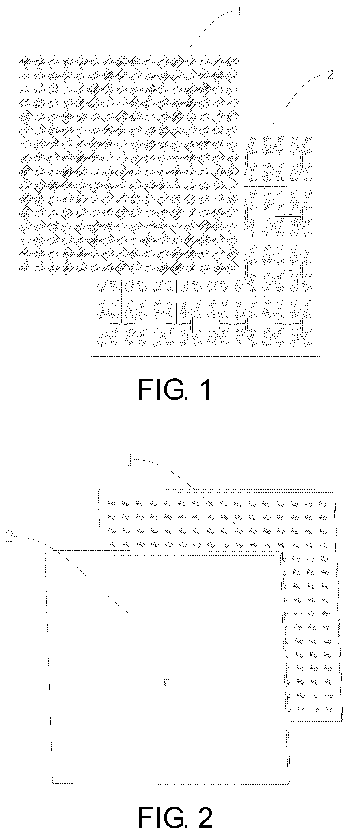
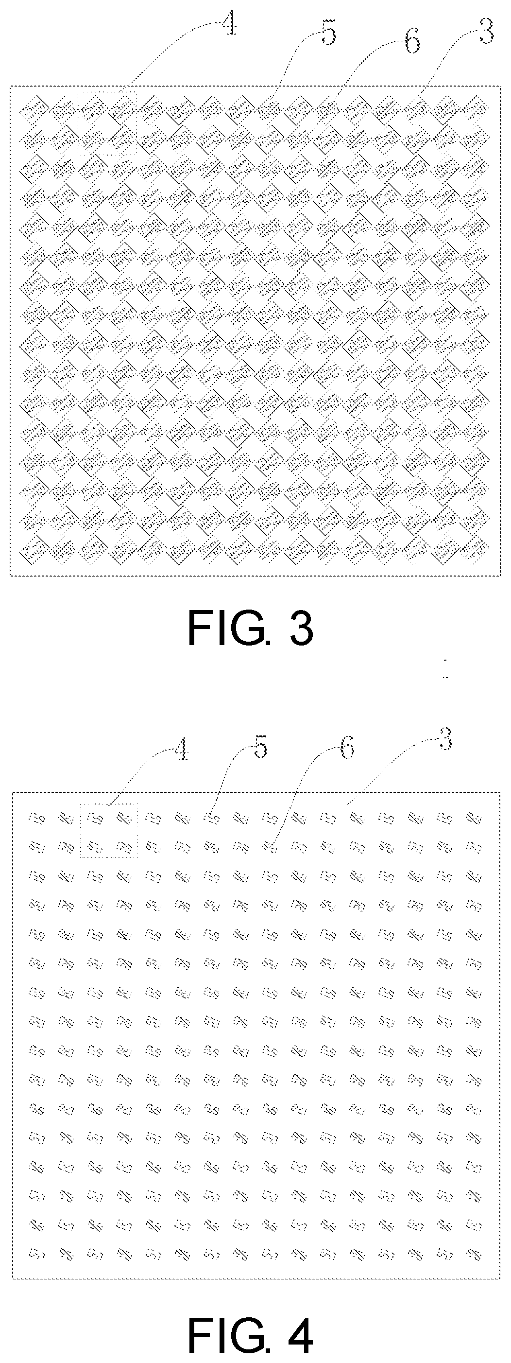
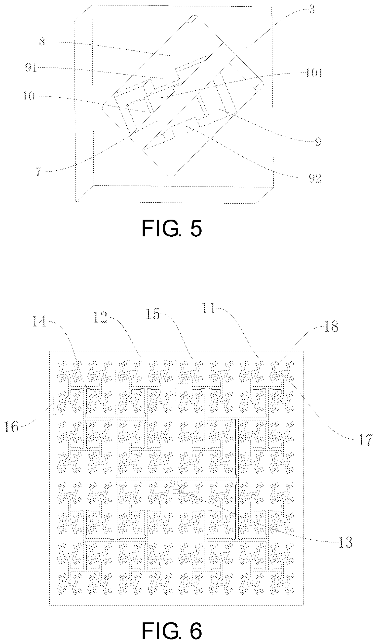
[0052]Embodiment: as shown in FIG. 1 and FIG. 2, a low-sidelobe plate array antenna comprises a radiation layer 1 and a feed layer 2, wherein the radiation layer 1 is superimposed on the feed layer 2, the feed layer 2 is used to output 4*n2 TE10 mode signals, the radiation layer 1 has 4*n2 input terminals and 4*n2 output terminals, the 4*n2 TE10 mode signals output by the feed layer 2 are accessed to the 4*n2 input terminals of the radiation layer 1 in a one-to-one correspondence, the 4*n2 output terminals of the radiation layer 1 are used to radiate the 4*n2 TE10 mode signals output by the feed layer 2 to a free space in a one-to-one correspondence, n=2(k-1), and k is an integer greater than or equal to 3; as shown in FIG. 3-FIG. 5, the radiation layer 1 comprises a first plate 3 and a radiation array disposed on the first plate 3, wherein the first plate 3 is a rectang...


PUM


Abstract

A low-sidelobe plate array antenna includes a radiation layer and a feed layer. The radiation layer is superimposed on the feed layer and includes a first plate and a radiation array disposed on the first plate. The radiation array is formed by n2 radiation units which are distributed in 2(k-1) rows and 2(k-1) columns. Each radiation unit in the radiation layer is constituted by two first radiation assemblies and two second radiation assemblies. Each first radiation assembly comprises a first rectangular bar, a first rectangular cavity, a second rectangular cavity and a third rectangular cavity. The first rectangular cavity, the second rectangular cavity and the third rectangular cavity in the first radiation assembly are stacked in presence of an azimuth deviation to form a three-layer coupled structure, and the first rectangular bar located in the first rectangular cavity can better restrain cross polarization and reduce the sidelobe.

Description

CROSS-REFERENCE TO RELATED APPLICATION[0001]This application claims the priority benefit of China application serial no. 202010417832.9, filed on May 18, 2020. The entirety of the above-mentioned patent application is hereby incorporated by reference herein and made a part of this specification.TECHNICAL FIELD[0002]The invention relates to a plate array antenna, in particular to a low-sidelobe plate array antenna.DESCRIPTION OF RELATED ART[0003]In recent years, high-performance array antennas which have a high sensitivity, a wide band, a low profile and a low sidelobe and characterized by multiple frequency bands and low costs have been widely used in the fields of radar, communication, remote sensing and metering, and spatial technology. Existing common array antennas mainly include micro-strip array antennas and plate array antennas.[0004]The micro-strip array antennas are featured by low profile, low cost and low weight and are easy to machine. However, when the frequency or ante...

Claims


Application Information

Patent Timeline
IPC IPC(8): H01Q15/00H01Q21/06H01Q21/00H01Q1/38H01Q25/02
CPCH01Q15/0053H01Q21/061H01Q25/02H01Q1/38H01Q21/0031H01Q21/064H01Q13/10H01Q1/36H01Q1/50H01Q13/18
Inventor YOU, YANGHUANG, JIFUZHANG, LINGYOU, QINGCHUNLU, YUNLONG
Owner NINGBO UNIV
Why Eureka
Try Eureka