Method and device for determining state of rechargeable battery

a rechargeable battery and state determination technology, applied in the direction of batteries, cell components, instruments, etc., can solve the problems of micro-short circuit detection by linking an increase in resistance caused, battery modules in the assembled battery deteriorate at different progress rates, and the assembled battery does not demonstrate a specified performance as a whole. achieve the effect of higher accuracy

Pending Publication Date: 2021-10-28
PANASONIC EV ENERGY CO LTD
View PDF5 Cites 1 Cited by
  • Summary
  • Abstract
  • Description
  • Claims
  • Application Information

AI Technical Summary

Benefits of technology

[0009]It is an objective of the present disclosure to provide a method and device for determining a state of a rechargeable battery with higher accuracy.

Problems solved by technology

However, the battery modules in the assembled battery deteriorate at different progress rates.
In such a case, the assembled battery does not demonstrate a specified performance as a whole due to a battery module that has deteriorated.
As described in Patent Document 1, detection of a sign of a micro-short circuit by linking an increase in resistance caused by a decrease in the electrolytic solution with the micro-short circuit is not sufficient to detect the sign of a micro-short circuit.

Method used


Image

  • Method and device for determining state of rechargeable battery
  • Method and device for determining state of rechargeable battery
  • Method and device for determining state of rechargeable battery

Examples


first embodiment

Overview of Embodiment

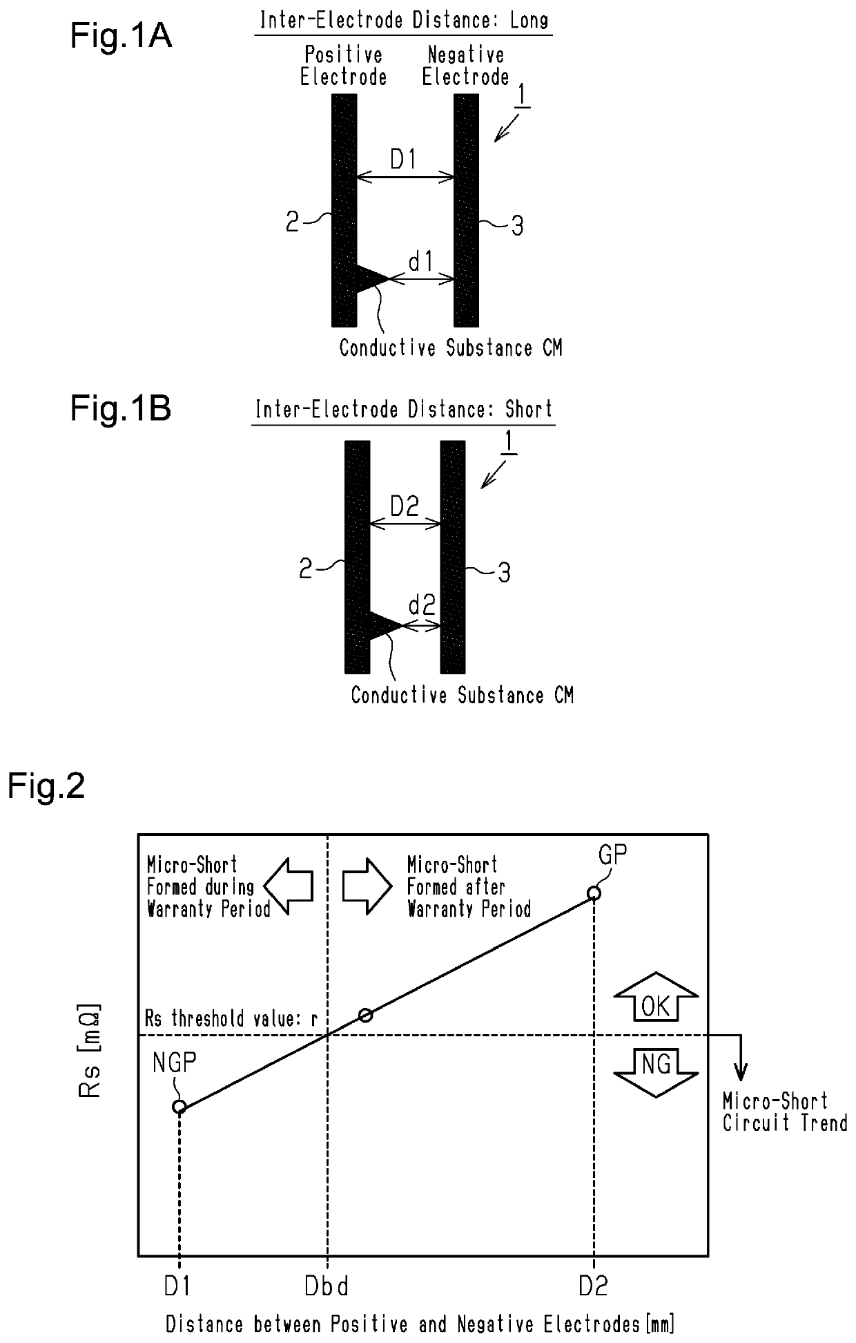
[0035]In the present embodiment, a method for determining a state of a rechargeable battery 1 and a rechargeable battery state determining device 10 use a technique that estimates an inter-electrode distance D between a positive electrode and a negative electrode to detect a rechargeable battery 1 that is likely to form a micro-short circuit in a short time after shipment.

[0036]The rechargeable battery 1 is, for example, a lithium-ion rechargeable battery or a nickel-metal hydride rechargeable battery. In the present embodiment, an on-board lithium-ion rechargeable battery will be described as an example.

[0037]FIG. 1A is a schematic diagram showing an inter-electrode distance D1 between a positive electrode 2 and a negative electrode 3 of a rechargeable battery 1 that is a conforming piece GP. FIG. 1B is a schematic diagram showing an inter-electrode distance D2 between a positive electrode 2 and a negative electrode 3 of a rechargeable battery 1 that is a non-...

second embodiment

Effect of Second Embodiment

[0093](4) The rechargeable battery state determining device has a simple configuration and thus is mountable on a vehicle. The state of a rechargeable battery that is on-board is determined even while the vehicle is in operation.

modified examples

[0094]The embodiments may be modified as follows.

[0095]In the embodiments, the flowchart of the process for determining the state of the rechargeable battery 1 shown in FIG. 7 is an example. The order and contents are not limited to those described in the embodiments. Unless specifically described, the flowchart shown in FIG. 7 may be executed in a similar or different order and may include an additional or alternative step. In an example, in the flowchart shown in FIG. 7, the self-discharge determination, the electrolytic solution determination, and the inter-electrode distance determination may be executed in a different order, and one of the self-discharge determination, the electrolytic solution determination, and the inter-electrode distance determination may be omitted.


PUM

PropertyMeasurementUnit
frequencyaaaaaaaaaa
frequencyaaaaaaaaaa
frequencyaaaaaaaaaa

Abstract

A rechargeable battery state determination method determines whether a rechargeable battery is in a micro-short-circuit-prone state, which is a state that is highly likely to form a micro-short circuit. The rechargeable battery state determination method includes measuring an electron transfer resistance of the rechargeable battery by applying a voltage or current having a predetermined or higher frequency to an electrode system of the rechargeable battery, determining whether an inter-electrode distance is satisfactory based on a comparison of the measured electron transfer resistance of the rechargeable battery with a predetermined lower limit threshold value, in which the determining whether an inter-electrode distance is satisfactory including determining that the inter-electrode distance is satisfactory when the measured electron transfer resistance of the rechargeable battery is greater than or equal to the lower limit threshold value, and determining that the rechargeable battery is a conforming piece when the inter-electrode distance is satisfactory.

Description

BACKGROUND1. Field[0001]The following description relates to a method and a device for determining a state of a rechargeable battery, more specifically, a method and a device for determining a state of a rechargeable battery with higher accuracy.2. Description of Related Art[0002]An electrically driven vehicle, which is, for example, an electric car, and a hybrid vehicle, which includes a motor and an engine as drive sources of the vehicle, use a rechargeable battery as a power supply. The rechargeable battery includes, for example, a lithium-ion rechargeable battery and a nickel metal hydride rechargeable battery. Such a rechargeable battery is formed by combining a number of battery cells. During normal manufacturing and handling, a predetermined number of battery cells are used as a single unit to form a battery module. Battery modules are combined to form an assembled battery, and the assembled battery is mounted on a vehicle. Deterioration of an assembled battery progresses to ...

Claims


Application Information

Patent Timeline
Patent Type & Authority Applications(United States)
IPC IPC(8): H01M10/48B60L58/12G01R31/3842H01M50/569
CPCH01M10/484B60L58/12H01M2220/20H01M50/569G01R31/3842G01R31/382G01R31/389G01R31/52Y02T10/70Y02E60/10
Inventor FUKUMA, TAMOTSUSUZUKI, HITOSHIKOBA, DAISUKE
Owner PANASONIC EV ENERGY CO LTD
Why Eureka
Try Eureka