
Passive Self-Ligation Bracket Assembly

a bracket and self-ligation technology, applied in the field of orthodontics, can solve the problems of long and extended treatment times, difficult to move/translate bracketed teeth along the archwire, and prolong treatment times

Pending Publication Date: 2021-10-28
PREMIER ORTHODONTIC DESIGNS LLLP
View PDF7 Cites 1 Cited by
  • Summary
  • Abstract
  • Description
  • Claims
  • Application Information

AI Technical Summary

Benefits of technology

The present invention is a passive self-ligation bracket system that allows for easy and accurate placement of orthodontic brackets on a patient's teeth. The system includes brackets with movable doors that align to the center level archwire slot line-up, and can be easily inserted and removed without distorting the archwire. The system also allows for an increase or decrease in the torque force output by changing the vertical height dimension between the superior and inferior surfaces of the archwire or the angle / slope of the upper and lower walls of the archwire slot relative to the horizontal plane. Overall, the system improves the efficiency and effectiveness of orthodontic treatment.

Problems solved by technology

Torque control (third order control) has been, and continues to be, a major obstacle in orthodontic treatment regimens that has often caused very long and extended treatment times.
At the time, clinicians had not yet realized that tightly tied archwires generated significant binding and friction which made it difficult to move / translate bracketed teeth along the archwire.
Although elastic ligature ties were very easy to place, elastic ligature ties still created significant binding and friction that slowed tooth movement and caused lengthened treatment times.
Unfortunately, ASL technology did not resolve the long felt need for achieving (third order) torque control, and ASL also required precise, and time consuming, archwire bending (intentionally bending torque bends into the archwire) to accomplish third order tooth torque control.
Design improvements for each of these three separate technologies are applicable only to that specific technology because the mechanics of one technology are not applicable to the mechanics of the others.
Despite technologic improvements, the most challenging issue for clinical orthodontics has remained the development of a bracket-archwire assembly that not only achieves first order and second order tooth control, but also achieves third order torque control while utilizing low biologic treatment forces throughout the treatment regimen.
This prior art technology was utilized sparingly due to the challenges of accurately achieving three-dimensional control of the teeth.
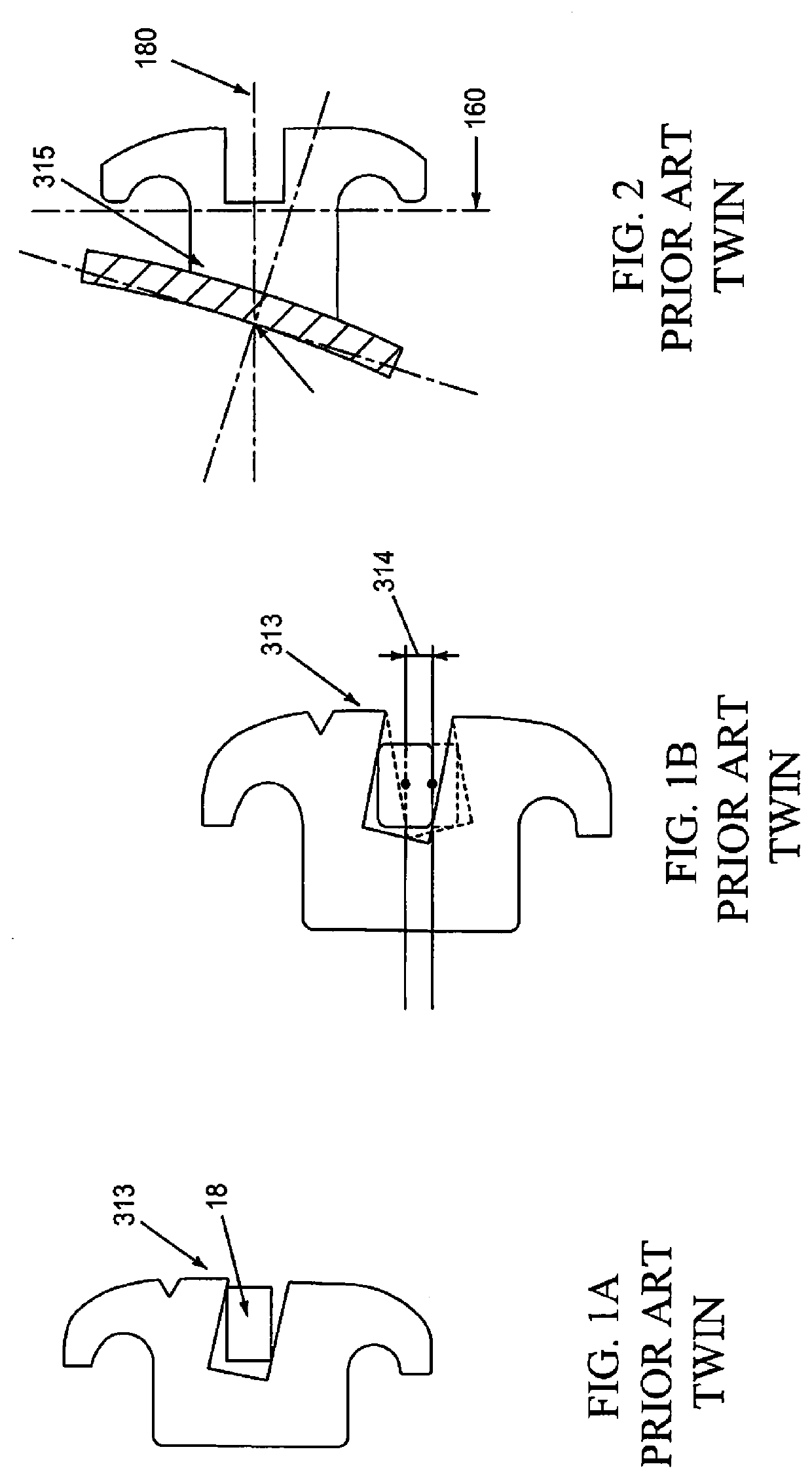
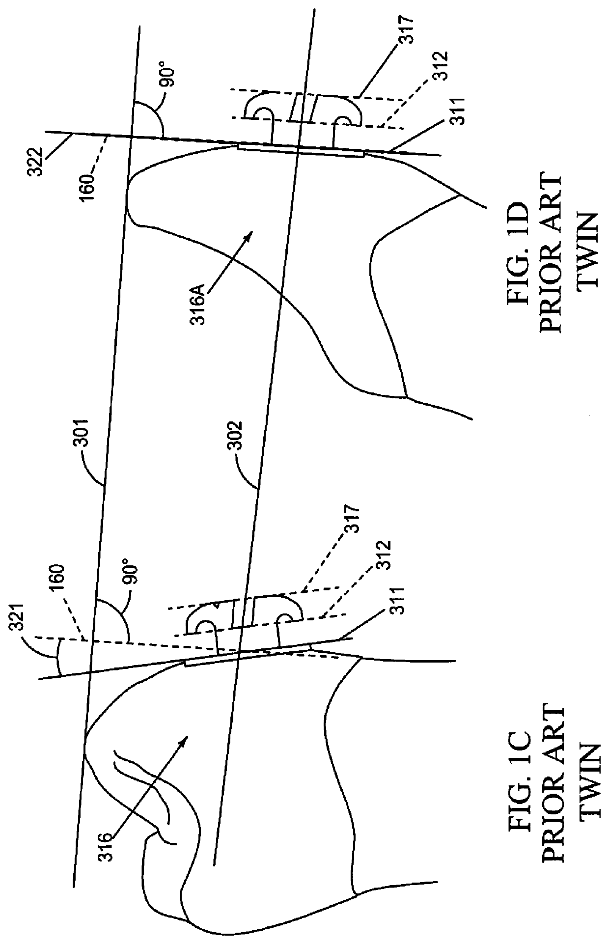
Different torques on adjacent teeth created a significant problem shown in FIG. 1B by lines drawn through the centers of high and low torqueing bracket slots highlighting how the centers of the slots move vertically a distance 314 which negatively impacts treatment mechanics and final tooth positions.
Another challenge for Twin Technology is that archwires 18 are securely tied against the base of the bracket slot with wire ligatures or elastic ties that cause / generate binding and friction that requires significantly higher treatment forces to move teeth.
Over time, clinicians have widely come to recognize that exerting excessive clinical forces limits / slows tooth movement; diminishes treatment planning options; dramatically lengthens treatment times; and can cause long-term tissue damage to bone and tissue.
Experienced clinicians often state, “If I have to make more than one torque bend in an archwire, I cannot predict what the end result will be.”
A second recognized drawback to Twin Brackets is the “Tying-In” or positionally securing archwires 18 frictionally against the base of the bracket slot.
These excessive forces negatively impact treatment options and contributes to a significant increase in numbers of patients requiring extractions (tooth removal).
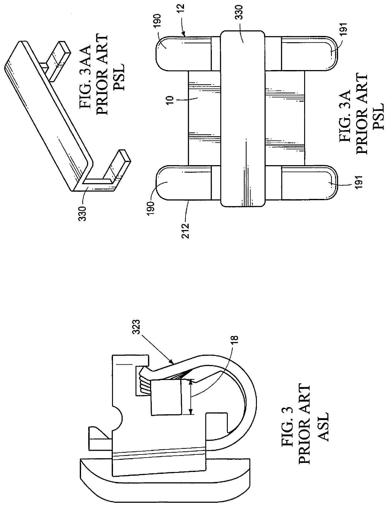
However, ASL still “seats” the archwire 18 directly and frictionally against the base of the bracket slot and still generates binding and friction, but to a lesser degree.
However, generating third order torque control still requires bending torque of bends into archwires by the clinician.
Although an improvement over Twin Technology, ASL did not resolve the need for third order tooth torque control.
However, utilizing known PSL brackets, during the last two-thirds of treatment still required significant time and effort to achieve final third Order “Torque Tooth Control” because finishing archwires still needed to be bent by clinicians to provide torque, which continued to lengthen treatment times more than desired by both patients and clinicians.
The Pletcher design provided improved strength, however, both the upper and lower dental arch brackets opened vertically or in the “sight-line” of the clinician making archwire positioning in the bracket slot challenging to visualize during door opening or closing.
This bracket did not resolve the need for clinicians to bend torque bends into archwires to accomplish third order Torque Control of the teeth.
Prior art FIGS. 5A, 53 and 5C of the PSL brackets of U.S. Pat. No. 5,464,347 show how the complexity of support for the door, while achieving standard or neutral torque in the bracket slot is challenging.
The result of installing an archwire 18 in these vertically misaligned slots is patient pain, and excessive biologic forces exerted on the teeth.

Method used


Image

  • Passive Self-Ligation Bracket Assembly
  • Passive Self-Ligation Bracket Assembly
  • Passive Self-Ligation Bracket Assembly

Examples


Embodiment Construction

[0134]This disclosure of the invention is submitted in furtherance of the Constitutional purposes of the U.S. Patent Laws “to promote the progress of science and useful arts”. (Article 1, Section 8).

[0135]The various surfaces / portions of the passive self-ligation (PSL) brackets, and related components, described herein have surfaces / portion designations may change depending upon the position of PSL bracket on the tooth in the maxillary jaw or mandibular jaw. In an effort to provide clarity, the reference frame herein, shall be relative to the patient's tongue. The following terms shall have the following meanings:

[0136]Upper Dental Arch: plurality of teeth within the maxillary jaw.

[0137]Lower Dental Arch: plurality of teeth within the mandibular jaw.

[0138]Occlusal Plane: biting surfaces of the teeth.

[0139]Facial: proximate to the lips / cheeks and opposite the tongue.

[0140]Lingual: proximate to the tongue.

[0141]Superior: vertically upper surface / portion.

[0142]Inferior: vertically lowe...


PUM


Abstract

A passive self-ligation bracket system for correcting malocclusions and tooth alignment, provides a first passive self-ligation bracket and a second passive self-ligation bracket, each of the first passive self-ligation bracket and the second passive self-ligation bracket having, a bracket body with a facial end portion, an opposing lingual end portion carrying a bracket base pad configured for adherence to a tooth, and a mid-body portion, a movable door engaged with the bracket body at the facial end portion, and means for exerting a predetermined torque on a tooth from the lingual end portion and from the mid-body portion, and the means for exerting the predetermined torque is defined in the mid-body portion, and has a center; and an archwire simultaneously slidably engaged within the means of the first and second passive self-ligation brackets exerts the predetermined torque.

Description

RELATED APPLICATIONS[0001]This US Non-Provisional (Utility) patent application claims priority to earlier filed U.S. Provisional Patent Application No. 63 / 015,528 filed on 25 Apr. 2020 and titled PASSIVE SELF-LIGATION BRACKETS. The entire contents of earlier filed U.S. Provisional Patent Application No. 63 / 015,528 is expressly incorporated herein, in its entirety, by this reference.[0002]Inventorship of earlier filed U.S. Provisional Patent Application No. 63 / 015,528 is the same as this US Non-Provisional patent application.[0003]Pursuant to USTPO Rules this priority claim is also being presented in the Application Data Sheet (ADS) filed with this US Non-Provisional patent application.TECHNICAL FIELD[0004]This invention relates to Orthodontics and more specifically to Passive Self-Ligation (PSL) brackets and methods for the use of such Passive Self-Ligation brackets during orthodontic treatment regimens for treatment and correction of malocclusions and irregular positions of teeth.B...

Claims


Application Information

Patent Timeline
IPC IPC(8): A61C7/28A61C7/14
CPCA61C7/287A61C7/145A61C7/14
Inventor DAMON, PAUL L.DAMON, DWIGHT H.
Owner PREMIER ORTHODONTIC DESIGNS LLLP
Learn More