Optical system, fundus examination apparatus, fundus imaging apparatus, and fundus examination system
a fundus examination and optical system technology, applied in the field of fundus imaging apparatus, can solve the problems of ghost flare, above-described conventional techniques, and is not possible to prevent ghost flare, and achieve the effect of suppressing the occurrence of ghost flar
- Summary
- Abstract
- Description
- Claims
- Application Information
AI Technical Summary
Benefits of technology
Problems solved by technology
Method used
Image


Examples
first embodiment
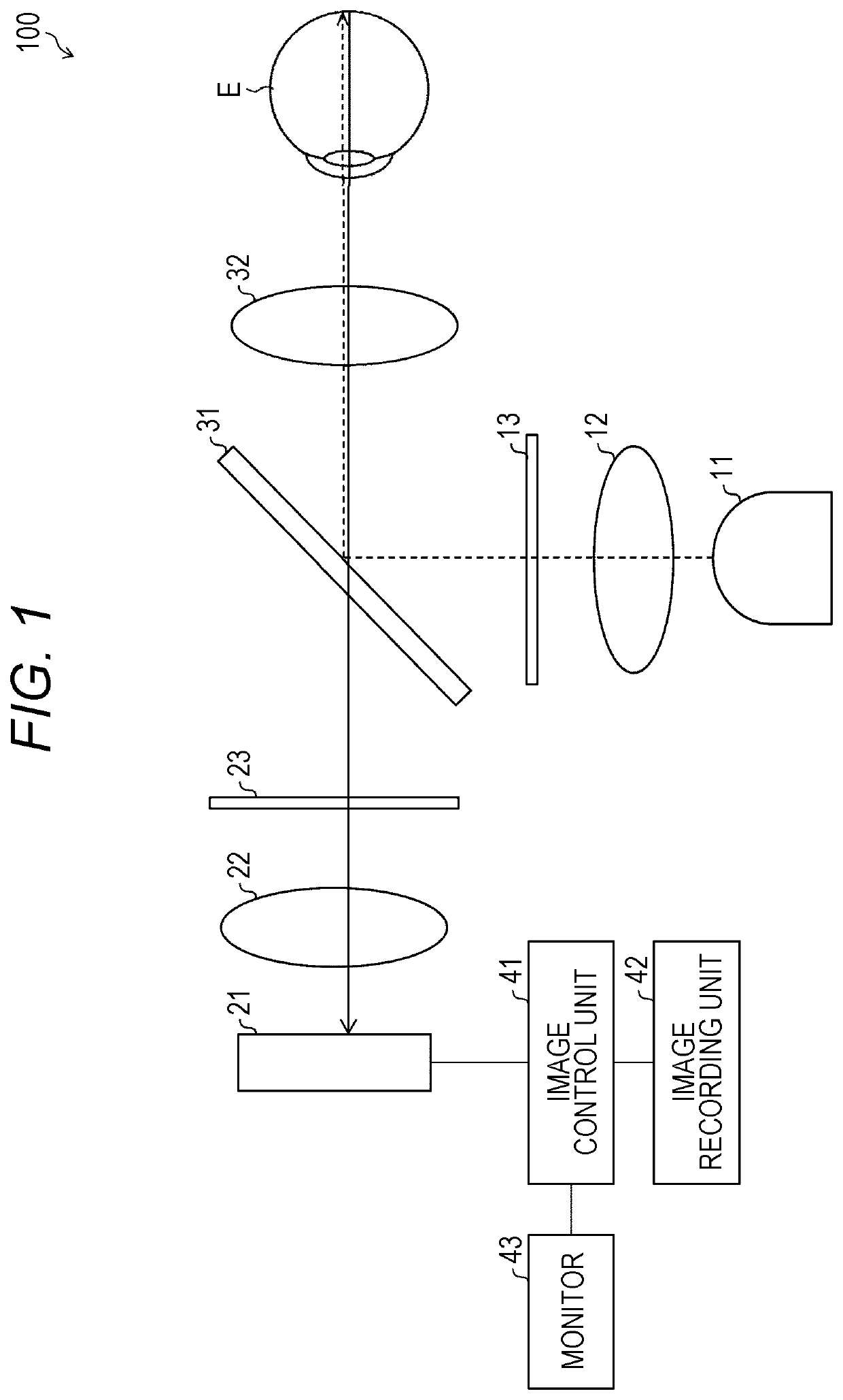
[0018]FIG. 1 is a view schematically showing an example of an optical system 100 according to the first embodiment of the present invention. As shewn in FIG. 1, the optical system 100 is an optical system for observing reflected light from a fundus of an eye E. The optical system 100 is an optical system of coaxial epi-illumination. The optical system 100 includes an irradiation unit, a light-acceptance unit, and a polarization control unit. The optical system 100 is an optical system of coaxial epi-illumination in which the optical axis of light irradiated to the eye E and the optical axis of reflected light from the eye E coincide with each other.
CONFIGURATION EXAMPLE
[0019]As shown in FIG. 1, the optical system 100 includes a light source 11, a lens 12, a first z-polarizer 13, a beam splitter 31, a lens 32, a second z-polarizer 23, a lens 22, and a camera 21. The camera 21 can transmit / receive data to / from an image control unit 41. The image control unit 41 is connected to an imag...
second embodiment
[0053]Other embodiments of the present invention will be described below. For convenience of explanation, members having the same functions as those described in the above embodiment are denoted by the same reference numerals, and description thereof will not be repeated.
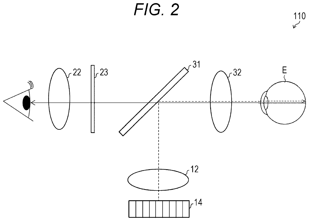
[0054]FIG. 2 is a view schematically showing an example of an optical system 110 according to a second embodiment of the present invention. The optical system 110 is an optical system of coaxial epi-illumination. As shown in FIG. 2, the optical system 110 is different from the optical system 100 of the first embodiment shown in FIG. 1 in that the optical system has a light source 14 and the second z-polarizer 23 as a polarization control unit. Therefore, in the present embodiment, only the points different from the first embodiment will be described in detail, and other details will be omitted.
[0055](Configuration Example)
[0056]As shown in FIG. 2, the optical system 110 includes the light source 14, the lens 12, the...
third embodiment
(Third Embodiment
[0065]Other embodiments of the present invention will be described below. For convenience of explanation, members having the same functions as those described in the above embodiment are denoted by the same reference numerals, and description thereof will not be repeated.
[0066]FIG. 3 is a view schematically showing an example of an optical system 120 according to a third embodiment of the present invention. The optical system 120 is an optical system of coaxial epi-illumination. As shown in FIG. 3, the optical system 120 is different from the optical system 100 of the first embodiment shown in FIG. 1 in that the optical system has a polarization beam splitter 33 as a polarization control unit. Therefore, in the present embodiment, only the points different from the first embodiment will be described in detail, and other details will be omitted.
[0067](Configuration Example)
[0068]As shown in FIG. 3, the optical system 120 includes the light source 11, the lens 12, the...
PUM
 Abstract
Description
Claims
Application Information
 - R&D
- Intellectual Property
- Life Sciences
- Materials
- Tech Scout
- Unparalleled Data Quality
- Higher Quality Content
- 60% Fewer Hallucinations
Browse by: Latest US Patents, China's latest patents, Technical Efficacy Thesaurus, Application Domain, Technology Topic, Popular Technical Reports.
© 2025 PatSnap. All rights reserved.Legal|Privacy policy|Modern Slavery Act Transparency Statement|Sitemap|About US| Contact US: help@patsnap.com