Monitoring apparatus and monitoring method

a monitoring apparatus and monitoring method technology, applied in the direction of electrical transducers, geographical information databases, signal processing, etc., can solve the problems of inability to meet the demands of simplification of the monitoring apparatus, the configuration of the apparatus is not suitable, and the processing time is not suitable, so as to prevent the configuration of the apparatus from becoming complicated, the monitoring method can be restrained from becoming complicated, and the processing time required for beam forming processing can be shortened

Inactive Publication Date: 2021-09-16
JTEKT CORP
View PDF3 Cites 0 Cited by
  • Summary
  • Abstract
  • Description
  • Claims
  • Application Information

AI Technical Summary

Benefits of technology

The patent is about a monitoring apparatus and method for monitoring a target region based on sound waves. The invention allows for real-time monitoring without adding too much complexity to the configuration of the apparatus. It uses map information to determine which areas to monitor and which direction to beamform, reducing the amount of processing required. The apparatus also has a reference signal for each target region, which helps to accurately detect abnormalities. Overall, this invention enables efficient and effective monitoring of multiple target regions in real-time.

Problems solved by technology

Therefore, the apparatus according to JP 2017-32488 A cannot meet the demands for the simplification of the monitoring apparatus.
In consequence, the apparatus according to JP 2013-15468 A makes the processing time from acquisition of the sound to the determination on abnormality long, and cannot meet the demands for the immediacy of making the determination on abnormality.
In particular, in the case where the scope of the abnormal region is narrowed to carry out monitoring in more detail, the number of lattice points needs to be increased, which leads to a further deterioration in the immediacy of making the determination on abnormality.
Besides, the monitoring apparatus of the disclosure performs the beam forming processing based on the map information, and hence can limit the regions to be subjected to the beam forming processing to the regions to be monitored (the regions to be subjected to the detection of abnormality).
Besides, the monitoring method of the disclosure includes the performance of the beam forming processing based on the map information, and hence can limit the regions to be subjected to the beam forming processing to the regions to be monitored (the regions to be subjected to the detection of abnormality).

Method used


Image

  • Monitoring apparatus and monitoring method
  • Monitoring apparatus and monitoring method
  • Monitoring apparatus and monitoring method

Examples


embodiments

[0023]One of the embodiments of the disclosure will be described hereinafter with reference to the drawings.

[0024]In the present disclosure, the term “sound wave” means an elastic wave propagating in a medium (e.g., a gas, a liquid, or a solid). The sound wave includes an ultrasonic wave (equal to or higher than 20 kHz) and an infrasonic wave (lower than 20 Hz) as well as “a sound” of audible frequencies for humans (equal to or higher than 20 Hz and lower than 20 kHz).

[0025]Configuration of Monitoring Apparatus

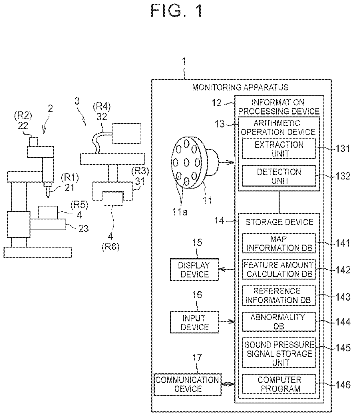
[0026]FIG. 1 is a schematic view showing a monitoring apparatus 1 according to the embodiment. The monitoring apparatus 1 is an apparatus that monitors a plurality of target regions based on sound waves. The monitoring apparatus 1 is installed in, for example, a place where an object to be worked (a work) is worked.

[0027]The target regions of the present embodiment include target regions R1 to R4 where parts (components) in which a device abnormality is estimated to occur, and...

modification example

[0069]While the embodiment of the disclosure has been described above, the disclosure can be subjected to various alterations other than the above-mentioned embodiment. A modification example according to the embodiment of the disclosure will be described hereinafter. In the following modification example, components identical to those of the embodiment are denoted by the same reference symbols respectively, and the description thereof will be omitted.

[0070]In the above-mentioned embodiment, the feature set FS1 is calculated in the signal processing process S41, and the feature amount included in the feature set FS1 and the reference amount included in the reference information N1 are compared with each other in the determination process S42. However, the signal processing process S41 may be omitted, and the specific sound pressure signal SP2 acquired in the extraction process S3 and the reference amount included in the reference information N1 may be directly compared with each oth...


PUM


Abstract

A monitoring apparatus includes a sound collecting device and an information processing device. The sound collecting device has a plurality of microphones arranged. The microphones convert sound waves emitted from the target regions into sound pressure signals respectively. The information processing device stores map information on positions of the target regions with respect to the sound collecting device, and extracts a specific sound pressure signal from the sound pressure signals for each of the target regions by subjecting the sound pressure signals to beam forming processing based on the map information.

Description

CROSS-REFERENCE TO RELATED APPLICATION[0001]This application claims priority to Japanese Patent Application No. 2020-041113 filed on Mar. 10, 2020, incorporated herein by reference in its entirety.BACKGROUND1. Technical Field[0002]The disclosure relates to a monitoring apparatus and a monitoring method for monitoring a plurality of target regions.2. Description of Related Art[0003]There is known an art of making a diagnosis of abnormality in an instrument based on a sound produced from the instrument. For example, Japanese Unexamined Patent Application Publication No. 2013-200144 (JP 2013-200144 A) discloses an art of subjecting a signal from a sound collector to various kinds of processing such as fast Fourier transformation to learn and diagnose a sample value. Japanese Unexamined Patent Application Publication No. 2001-151330 (JP 2001-151330 A) discloses an art that relates to a belt conveyor abnormality diagnosis device and that uses an omnidirectional microphone and a direction...

Claims


Application Information

Patent Timeline
Patent Type & Authority Applications(United States)
IPC IPC(8): H04R29/00H04R3/00H04R1/32
CPCH04R29/005H04R1/326H04R3/005G06F16/29H04R2430/20G06F2218/18G06F2218/10
Inventor STOIMENOV, BOYKONOZAKI, MIKIO
Owner JTEKT CORP
Why Eureka
Try Eureka