Flexible electrode and fabrication method therefor

Pending Publication Date: 2021-08-19
NAT SYNCHROTRON RADIATION RES CENT
View PDF0 Cites 0 Cited by
  • Summary
  • Abstract
  • Description
  • Claims
  • Application Information

AI Technical Summary

Benefits of technology

The present invention aims to improve the electrodes of batteries or energy storage elements used in wearable electronic devices. It has the advantage of better energy efficiency and reduced environmental harm as it uses water as a solvent, instead of potentially harmful organic solvents.

Problems solved by technology

In other words, not only manufactured products need to be harmless to human bodies, but also lowest energy consumption (low carbon) and least environmental harm are required during the entire manufacturing, which is a great challenge for the manufacturing industry.

Method used


Image

  • Flexible electrode and fabrication method therefor
  • Flexible electrode and fabrication method therefor
  • Flexible electrode and fabrication method therefor

Examples


first embodiment

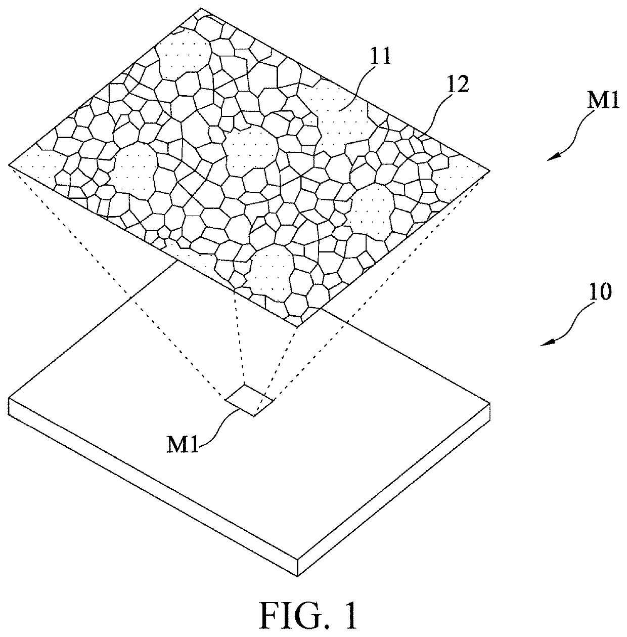
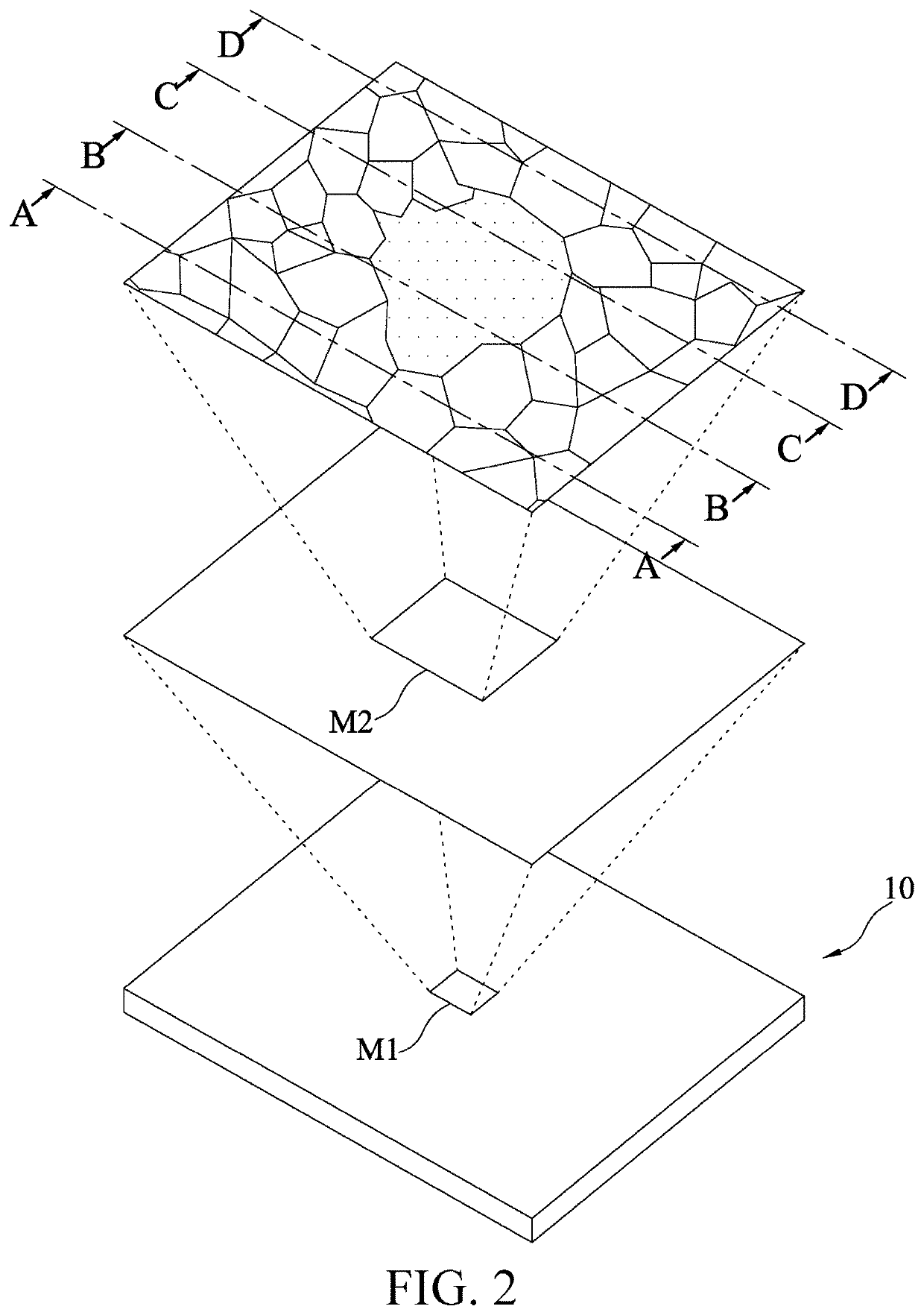
[0037]FIG. 1 and FIG. 2 are respectively a schematic diagram (1) and a schematic diagram (2) of a microstructure of a flexible electrode according to the present invention, which illustrate an exemplary flexible electrode 10 and a surface interior. The flexible electrode 10 in this embodiment includes an organic soft matrix (an organic-phase domains) 11 and a plurality of silicate lamellar blocks (an inorganic-phase domains) 12. The organic soft matrix (the organic-phase domains) 11 is mainly composed of a conductive polymer (for example, PEDOT:PSS, PANI, or PPY) and a binder. The binder (for example, PVA, PEO, PAMM, PVAC, or PVP) used in this embodiment is water-soluble and ionically conductive. FIG. 3A to FIG. 3D show interiors of cross-sections of different positions (lines AA, BB, CC, and DD marked in FIG. 2) on an exemplary flexible electrode 10. Each of the silicate lamellar blocks 12 is composed of a plurality of stacked silicate lamellae 121. A direction (shown in FIG. 3A to...

second embodiment

[0040]As shown in FIG. 4, in a second embodiment, first capacitively active materials 122 are adsorbed between at least a part of the silicate lamellae 121. The first capacitively active materials 122 are selected from transition metal ions (such as iron, cobalt, nickel, and the like, or a mixture thereof), especially from nitrate, sulfate, acetate or chloride of a transition metal.

third embodiment

[0041]As shown in FIG. 5, in a third embodiment, the organic soft matrix (the organic phase domain) 11 further includes second capacitively active materials 112. The second capacitively active materials 112 are selected from transition metal nanoparticles and transition metal oxide particles, such as manganese oxides, cobalt oxides, vanadium oxides, or the like.


PUM

PropertyMeasurementUnit
Molar densityaaaaaaaaaa
Particle sizeaaaaaaaaaa

Abstract

A flexible electrode and a fabrication method therefor are provided. The flexible electrode is formed by mixing organic-soft-matrix with inorganic-hard-material. The inorganic-hard-material is composed of silicate lamellar blocks and electrochemically active materials. Each of the silicate lamellar blocks is formed by multiple stacked nano-scaled sheet-like silicate lamellae. The organic-soft-matrix includes conductive polymer and binder. The binder is water-soluble and ionically conductive. The flexible electrode has a floor-ramp like opened-perforated layer structure formed by hierarchically aggregated inorganic silicate lamellar blocks, and pores of the opened-perforated layer structure are filled with the organic-soft-matrix, so as to form a network channel structure having organic phase and inorganic phase interlaced with each other. The floor-ramp like opened-perforated layer structure composed of aggregated inorganic silicate lamellar blocks contributes to stiffness of the flexible electrode, and the conductive polymer and the binder in the organic-soft-matrix respectively form electron channels and ion channels in the flexible electrode.

Description

CROSS-REFERENCE TO RELATED APPLICATION[0001]This non-provisional application claims priority under 35 U.S.C. § 119(a) to Patent Application No. 109105232 filed in Taiwan, R.O.C. on Feb. 18, 2020, the entire contents of which are hereby incorporated by reference.BACKGROUNDTechnical Field[0002]The present invention relates to a flexible electrode and a fabrication method thereof, and in particular, to a flexible electrode including inorganic silicate minerals and organic polymers and a fabrication method thereof.Related Art[0003]In recent years, wearable electronic devices such as a flexible display, an electronic skin, smart clothing, a smart watch, and the like are gradually popular, which are worn on human bodies in direct contact with human clothes and even skins. Therefore, compared with traditional portable electronic devices, safety and non-toxicity of batteries or energy storage elements of such wearable electronic devices need to be further emphasized in addition to energy de...

Claims


Application Information

Patent Timeline
IPC IPC(8): H01B1/12B29C45/00B29C45/17H01B1/08
CPCH01B1/124B29C45/0001B29K2509/02H01B1/122H01B1/08B29C45/17H01G11/22H01G11/26H01G11/86C25D7/0614C25D5/56B29L2031/3406
Inventor CHUANG, WEI-TSUNGGUO, RONG-HAODENG, MING-JAY
Owner NAT SYNCHROTRON RADIATION RES CENT
Why Eureka
Try Eureka