
Casing

a technology of turbofan and casing, which is applied in the direction of sustainable transportation, mechanical equipment, machines/engines, etc., can solve the problems of high thermodynamic efficiency, large fan diameter, and fuel burn

Active Publication Date: 2021-08-05
ROLLS ROYCE PLC
View PDF0 Cites 0 Cited by
  • Summary
  • Abstract
  • Description
  • Claims
  • Application Information

AI Technical Summary

Benefits of technology

This design enhances the structural integrity and reduces distortion of the core engine casing, preventing unwanted bending and maintaining efficiency while minimizing weight penalties.

Problems solved by technology

High OPR results in high thermodynamic efficiency, and so low fuel burn.
However, high OPR engine cores (having a large number of compressor stages) and / or high bypass ratios can result in a relatively large diameter fan, and a relatively long and thin engine core.
Such a core geometry can be susceptible to flexing in flight, which can result in rotor blade tip rubs (potentially resulting in damage) and / or excessive blade tip clearances being required (resulting in an adverse impact on efficiency).
Increasing the engine core stiffness by using additional bracing can result in engine weight penalties, which again detracts from the overall aircraft level reduction in fuel consumption provided by high bypass ratios and / or high OPR.
However, with the geared architecture, the core gas path and core engine casing remain at a relatively low diameter, with the resulting slender core casing line subject to high carcass distortion, with associated tip clearance (SFC penalties) and potential shaft and bearing misalignment problems.

Method used


Image

  • Casing
  • Casing
  • Casing

Examples


Embodiment Construction

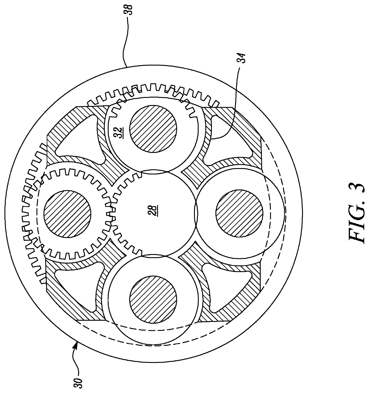
[0067]FIG. 1 illustrates a gas turbine engine 10 having a principal rotational axis 9. The engine 10 comprises an air intake 12 and a propulsive fan 23 that generates two airflows: a core airflow A and a bypass airflow B. The gas turbine engine 10 comprises a core 11 that receives the core airflow A. The engine core 11 comprises, in axial flow series, a low pressure compressor 14, a high-pressure compressor 15, combustion equipment 16, a high-pressure turbine 17, a low pressure turbine 19 and a core exhaust nozzle 20. A nacelle 21 surrounds the gas turbine engine 10 and defines a bypass duct 22 and a bypass exhaust nozzle 18. The bypass airflow B flows through the bypass duct 22. The fan 23 is attached to and driven by the low pressure turbine 19 via a shaft 26 and an epicyclic gearbox 30.

[0068]In use, the core airflow A is accelerated and compressed by the low pressure compressor 14 and directed into the high pressure compressor 15 where further compression takes place. The compres...


PUM


Abstract

A gas turbine engine comprising a planetary gear train, and a core engine casing. The gear train has a ratio of greater than approximately 3.0, with an input to the gear train being operatively connected to the compressor section, and an output from the gear train being operatively connected to the fan. The core engine casing encloses the compressor section and the turbine section. The fan has a diameter F, and the core engine casing has a diameter C. The core engine casing diameter C varies along an axial length of the core engine casing, and a ratio (C / F) of the core engine casing diameter C to the fan diameter F is within the range 0.2<(C / F)<0.4, along an axial length of the core engine casing.

Description

CROSS-REFERENCE TO RELATED APPLICATIONS[0001]This application is a divisional of, and claims priority under 35 USC § 120 to, U.S. non-provisional application 16 / 351,841 filed Mar. 13, 2019, and based s upon and claims priority under 35 USC § 119 to British Patent Application No. GB 1805764.6, filed on Apr. 6, 2018. Each of the above-identified patent applications is hereby incorporated by reference in its entirety.BACKGROUNDTechnical Field[0002]The present disclosure relates to a turbofan casing and particularly, but not exclusively, to a turbofan casing for a geared turbofan gas turbine engine.DESCRIPTION OF THE RELATED ART[0003]Aircraft gas turbine engines typically comprise a gas turbine engine core and a core driven fan enclosed within a fan nacelle. Air flows through the fan in use, and is divided into two airflows downstream, namely a bypass flow and a core flow. The ratio between the mass flow rate of air in the bypass flow to the mass flow rate of airflow of the core flow is...

Claims


Application Information

Patent Timeline
Patent Type & Authority Applications(United States)
IPC IPC(8): F02C7/36F02C3/06F02C3/107F02K3/06
CPCF02C7/36F02C3/06F05D2260/40311F02K3/06F05D2240/14F02C3/107Y02T50/60F01D25/24
Inventor STRETTON, RICHARD G.O'HANRAHAN, TIM
Owner ROLLS ROYCE PLC
Learn More