
Injection unit for a shaping machine having and a shaping machine comprising such an injection unit

a technology of injection unit and shaping machine, which is applied in the field of injection unit for shaping machine and shaping machine, can solve the problems of flexural warping of plate, direct influence of linear drive, etc., and achieve the effect of reducing stresses

Active Publication Date: 2021-07-22
ENGEL AUSTRIA
View PDF0 Cites 0 Cited by
  • Summary
  • Abstract
  • Description
  • Claims
  • Application Information

AI Technical Summary

Benefits of technology

The invention aims to reduce the stress placed on linear drives by bending moments, which is currently higher than desired. The clearances between the bearing element and the transmission element also prevent any wedging of these components. The additional decoupling of the linear drives from the bearing element also allows for better force transmission with lower material usage and smaller structural sizes. Overall, this results in higher efficiency and lower wear and stress on the linear drives.

Problems solved by technology

A disadvantage in that respect is that upon deformation of the bearing element that deformation directly affects the linear drives.
In the case of plate-shaped bearing elements the effect of the force generally results in flexural warping of the plate.

Method used


Image

  • Injection unit for a shaping machine having and a shaping machine comprising such an injection unit
  • Injection unit for a shaping machine having and a shaping machine comprising such an injection unit

Examples


Embodiment Construction

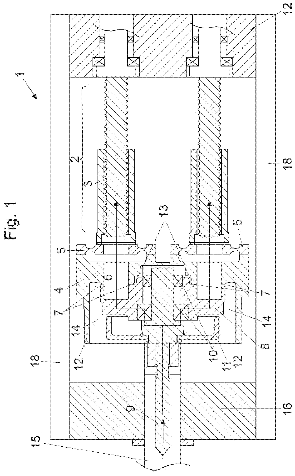
[0040]FIG. 1 shows an embodiment of an injection unit 1 according to the invention in cross-section, the injection unit 1 having two linear drives. In this embodiment the linear drives are in the form of spindle drives 2.

[0041]The spindle drives 2 are respectively connected to the transmission element 4 in motion-transmitting relationship by way of a spindle nut 3.

[0042]Arranged between the transmission element 4 and the spindle nut 3 are measuring diaphragms 5, by which it is possible to measuringly detect a force between the spindle drive 2 and the transmission element 4.

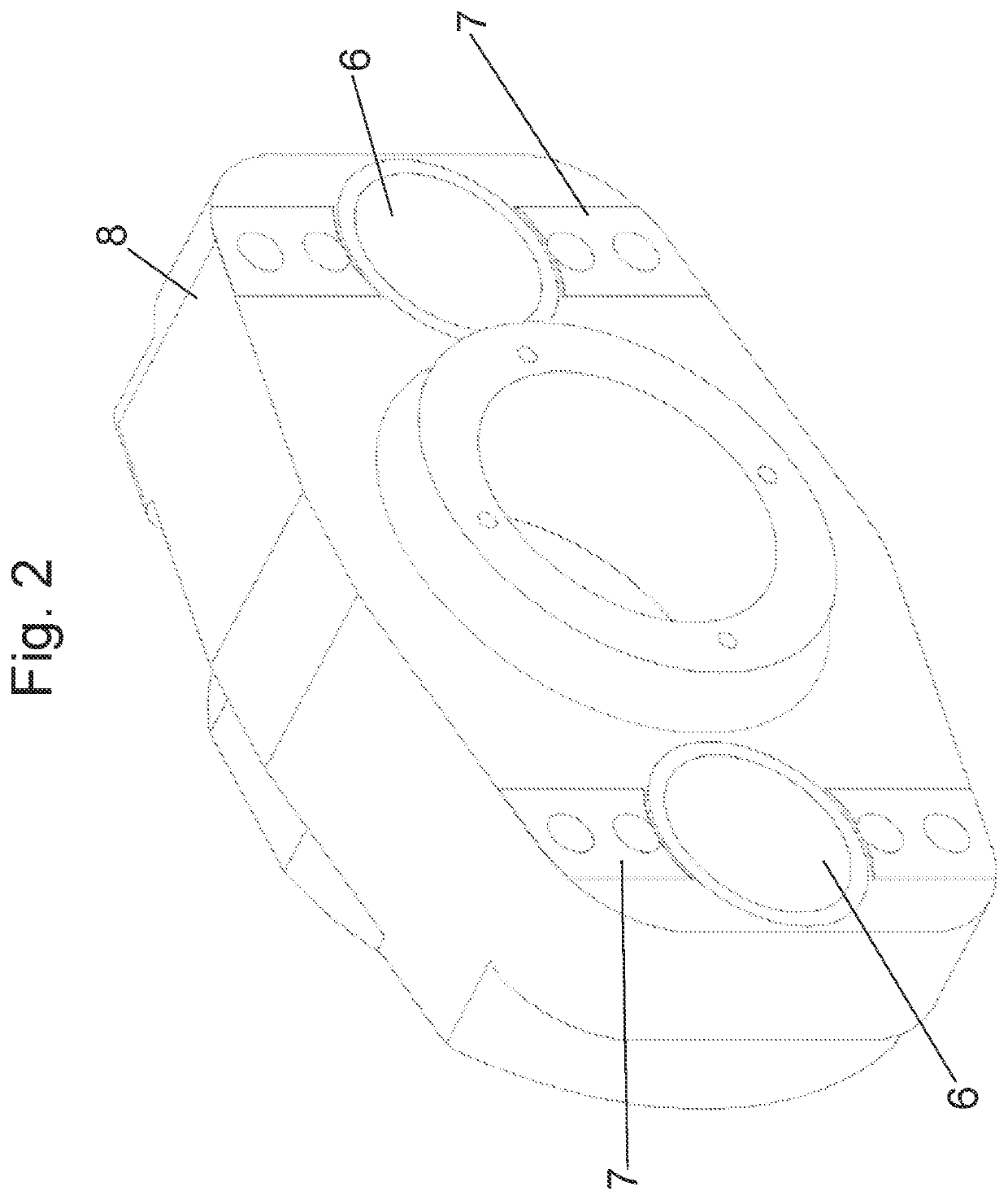
[0043]In addition the transmission element 4 has openings 6 which are adapted to receive the spindles of the spindle drives 2 in a retracted position—more precisely: a plasticizing position.

[0044]The transmission element 4 is connected to the bearing element 8 by way of the contact surfaces 7, in which case a force can be transmitted from the spindle drive 2 to the bearing element 8 by way of the transmission elem...


PUM

PropertyMeasurementUnit
Forceaaaaaaaaaa
Massaaaaaaaaaa

Abstract

An injection unit for a shaping machine includes an injection element suitable for introducing a plasticized material into a mould tool by a linear movement of the injection element. The injection element is coupled in linear motion-transmitting relationship to a bearing element, and at least two linear drives are adapted to exert a force on the injection element by the bearing element. The force can be transmitted by a transmission element from the at least two linear drives to the bearing element and thus to the injection element, and at least one clearance is arranged between the bearing element and the transmission element so that deformations of the bearing element are not transmitted to the transmission element or are transmitted to a reduced degree.

Description

BACKGROUND OF THE INVENTION[0001]The present invention concerns an injection unit for a shaping machine and a shaping machine comprising such an injection unit.[0002]The term shaping machines in that respect can be used to denote injection moulding machines, injection presses, presses or the like. Hereinafter the state of the art is to be represented by means of an injection moulding machine. A similar consideration applies to general shaping machines.[0003]Injection units of the general kind set forth have an injection element suitable for introducing a plasticized material into a mould tool by a linear movement, wherein the injection element is coupled in linear motion-transmitting relationship to a bearing element and at least two linear drives are adapted to exert a force on the injection element by way of the bearing element.[0004]Injection units are generally used to inject a plasticized material (for example a thermoplastic material) into a mould tool.[0005]Plasticization of ...

Claims


Application Information

Patent Timeline
IPC IPC(8): B29C45/53B29C45/54B29C45/60B29C45/17
CPCB29C45/531B29C45/1775B29C45/60B29C45/54B29C45/58B29C45/5008B29C2045/504
Inventor DIRNEDER, FRANZEPPICH, STEPHANSTRASSER, ROBERTHACKL-LEHNER, GERHARDBALKA, CHRISTOPHPERNKOPF, FRIEDRICHBOEHM, GERNOT
Owner ENGEL AUSTRIA
Learn More