
Separator assembly used for fuel cell

Active Publication Date: 2021-06-24
NOK CORP +1
View PDF0 Cites 0 Cited by
  • Summary
  • Abstract
  • Description
  • Claims
  • Application Information

AI Technical Summary

Benefits of technology

The present invention is a separator assembly for fuel cells that aims to improve sealing performance. It achieves this by reducing variations in surface pressure in the bead seal section, which ensures a consistent pressure across the entire periphery of the assembly. This results in improved performance and reduced variation in the surface pressure of the bead seal section.

Problems solved by technology

In the bead seal section 121, a variation of the reaction force leads to a variation of surface pressure, and resultantly may affect the sealing performance.

Method used


Image

  • Separator assembly used for fuel cell
  • Separator assembly used for fuel cell
  • Separator assembly used for fuel cell

Examples


example 1

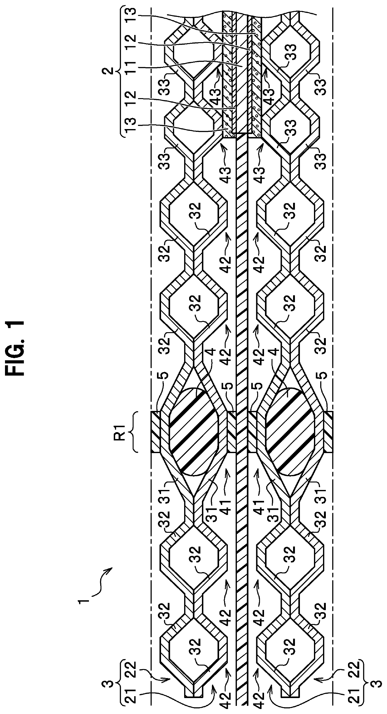
[0022]The fuel cell 1 is a member that generates power through chemical reaction between hydrogen (fuel gas) supplied from an anode side and oxygen (oxidant gas) supplied from a cathode side. A fuel cell stack is formed by arranging multiple fuel cells 1 side by side and applying a predetermined compressing load to the fuel cells 1 in a thick direction thereof. FIG. 1 illustrates the fuel cell 1 under the condition where a predetermined compressing load is applied.

[0023]The membrane electrode assembly (MEA) 2 includes an electrolyte membrane 11, electrode catalyst layers 12 and 12, and gas diffusion layers 13 and 13. The electrolyte membrane 11 spreads outside the gas diffusion layers 13. Here, a portion of the electrolyte membrane 11 spreading outside the gas diffusion layers 13 may be a resin film (resin flame member) in some cases.

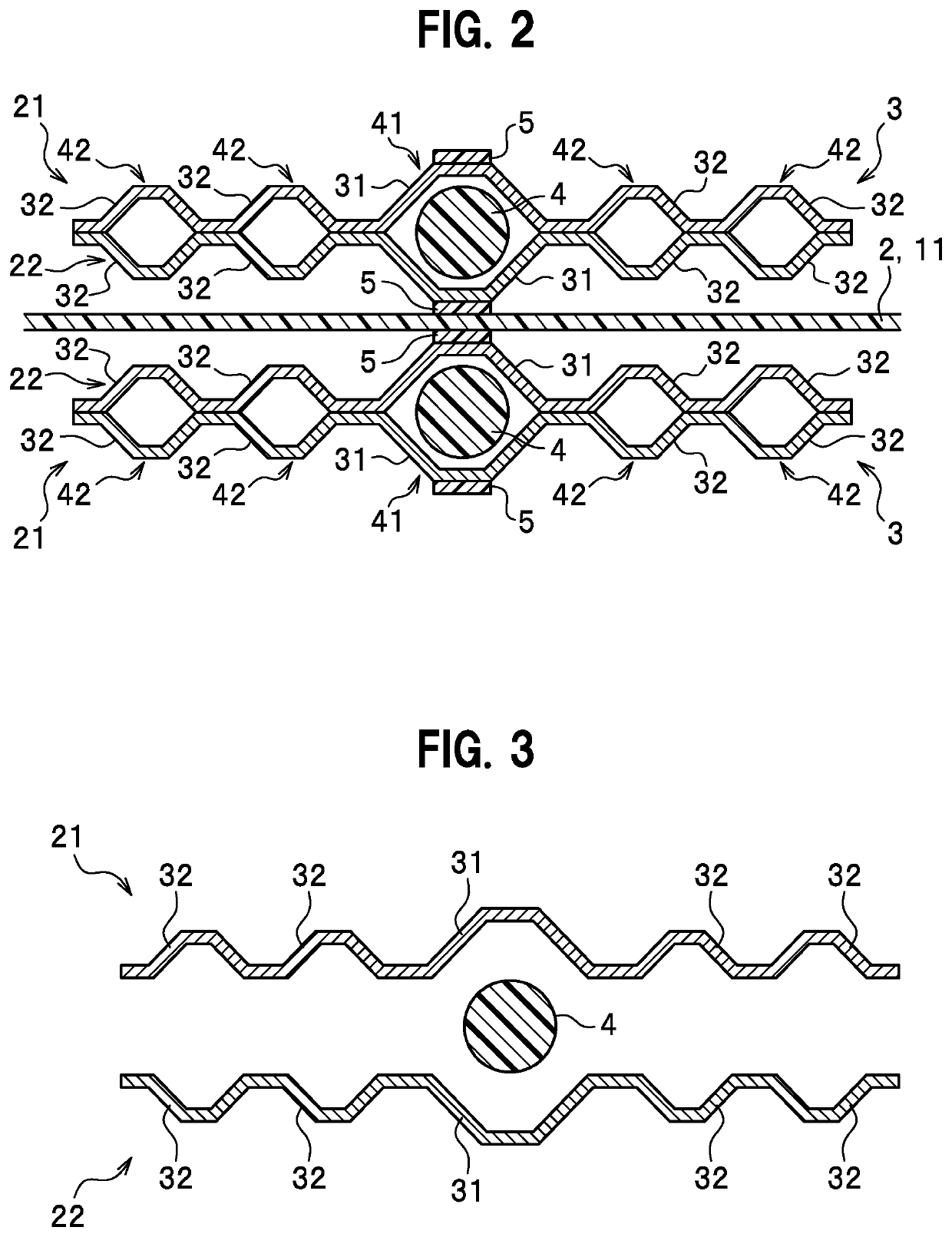
[0024]The separator assemblies 3 are plate-shaped members arranged on one and the other sides (the lower and upper sides in FIG. 1) of the membrane ele...

example 2

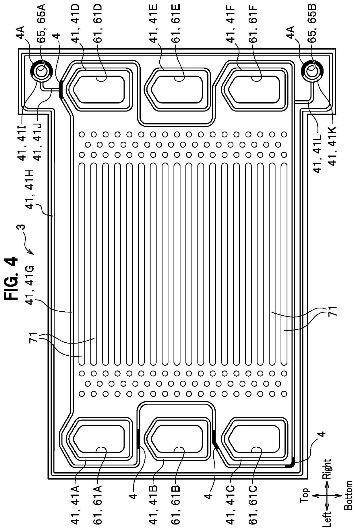
[0044]In Example 2 illustrated in FIGS. 4, 5A, and 5B, description is given of an example of layout locations of elastic bodies 4 and 4A in a separator assembly 3 used for a fuel cell. For convenience of description, “top and bottom” and “right and left” in FIG. 4 follow arrows in FIG. 4.

[0045]As illustrated in FIG. 4, the separator assembly 3 in Example 2 includes multiple bead seal sections 41, multiple elastic bodies 4 and 4A, multiple first communication holes 61, and multiple second communication holes 65.

[0046]The first communication holes 61 are holes which extend through the separator assembly in the thickness direction of the separators and which allows a reaction gas or a coolant to flow through the separator assembly 3. The shape of each first communication hole 61 is a polygonal shape in the present example, but may be any other shape such as a circular shape or an elliptic shape. The number of the first communication holes 61 is not particularly limited. In the present ...


PUM

PropertyMeasurementUnit
Lengthaaaaaaaaaa
Thicknessaaaaaaaaaa
Shapeaaaaaaaaaa

Abstract

A separator assembly used for a fuel cell includes one pair of metal separators joined together and including a bead seal section including one pair of seal bead portions projecting in opposite directions respectively, an elastic body disposed in the bead seal section, and a first communication hole which extends through the separator assembly in a thickness direction of the separator assembly and which allows a reaction gas or a coolant to flow through the separator assembly. The bead seal section is disposed along an outer periphery of the separator assembly and along a shape of the first communication hole. The elastic body of a predetermined length is disposed in the bead seal section.

Description

CROSS REFERENCE TO RELATED APPLICATIONS[0001]This application claims the foreign priority benefit under 35 U.S.C. § 119 of Japanese patent application No. 2019-231102 filed on Dec. 23, 2019, the entire disclosure of which is incorporated herein by reference.BACKGROUND OF THE INVENTION1. Field of the Invention[0002]The present invention relates to a separator assembly used for a fuel cell.2. Description of the Related Art[0003]For example, Japanese Patent Application Publication No. 2017-139218 (Patent Literature 1) discloses a fuel cell including separator assemblies.[0004]The fuel cell includes a membrane electrode assembly and one pair of separator assemblies between which the membrane electrode assembly is held (see Patent Literature 1).[0005]FIG. 6 is a cross-sectional view illustrating an example of a separator assembly related to Patent Literature 1. As illustrated in FIG. 6, a separator assembly 120 is formed by joining a first metal separator 101 and a second metal separator...

Claims


Application Information

Patent Timeline
IPC IPC(8): H01M8/0276H01M8/0258H01M8/0206
CPCH01M8/0276H01M8/0206H01M8/0258H01M8/0273H01M8/0265H01M8/0284Y02E60/50
Inventor SUZUKI, KENTOISHIDA, KENTARONUNOKAWA, KAZUOGIGA, AKIHITO
Owner NOK CORP
Learn More