
Metal gasket

a technology of metal gaskets and gaskets, which is applied in the direction of engine seals, sealing arrangements, machines/engines, etc., can solve the problems of inability to obtain adequate sealing performance, low rigidity of engine members, so as to achieve easy deformation, equal sealing surface pressure, and large compression resistance

Active Publication Date: 2012-05-29
ISHIKAWA GASKET CO LTD
View PDF4 Cites 14 Cited by
  • Summary
  • Abstract
  • Description
  • Claims
  • Application Information

AI Technical Summary

Benefits of technology

"The metal gasket described in this patent has a unique structure that allows for excellent sealing performance and prevents deformation of the sealing surface. The gasket includes two or more sheets of metal structural plates that are laminated together. The inner-periphery side bead has a smaller compression resistance than the other portions, while the outer-periphery side bead has a larger compression resistance. This results in a sealing surface pressure that is approximately equal all around the sealing bore, preventing any deformation of the sealing surface. The gasket also has a unique design that allows for flex control and compatibility with various joint surfaces. Overall, the metal gasket provides consistent sealing performance and excellent sealing abilities."

Problems solved by technology

Due to a recent lightweight and downsized engine, the engine has a low rigidity, and engine members have also low rigidities.
If the cylinder bore, flange or the like is deformed, a sealing means such as beads or the like does not function completely, so that adequate sealing performance cannot be obtained.

Method used


Image

  • Metal gasket
  • Metal gasket
  • Metal gasket

Examples


first embodiment

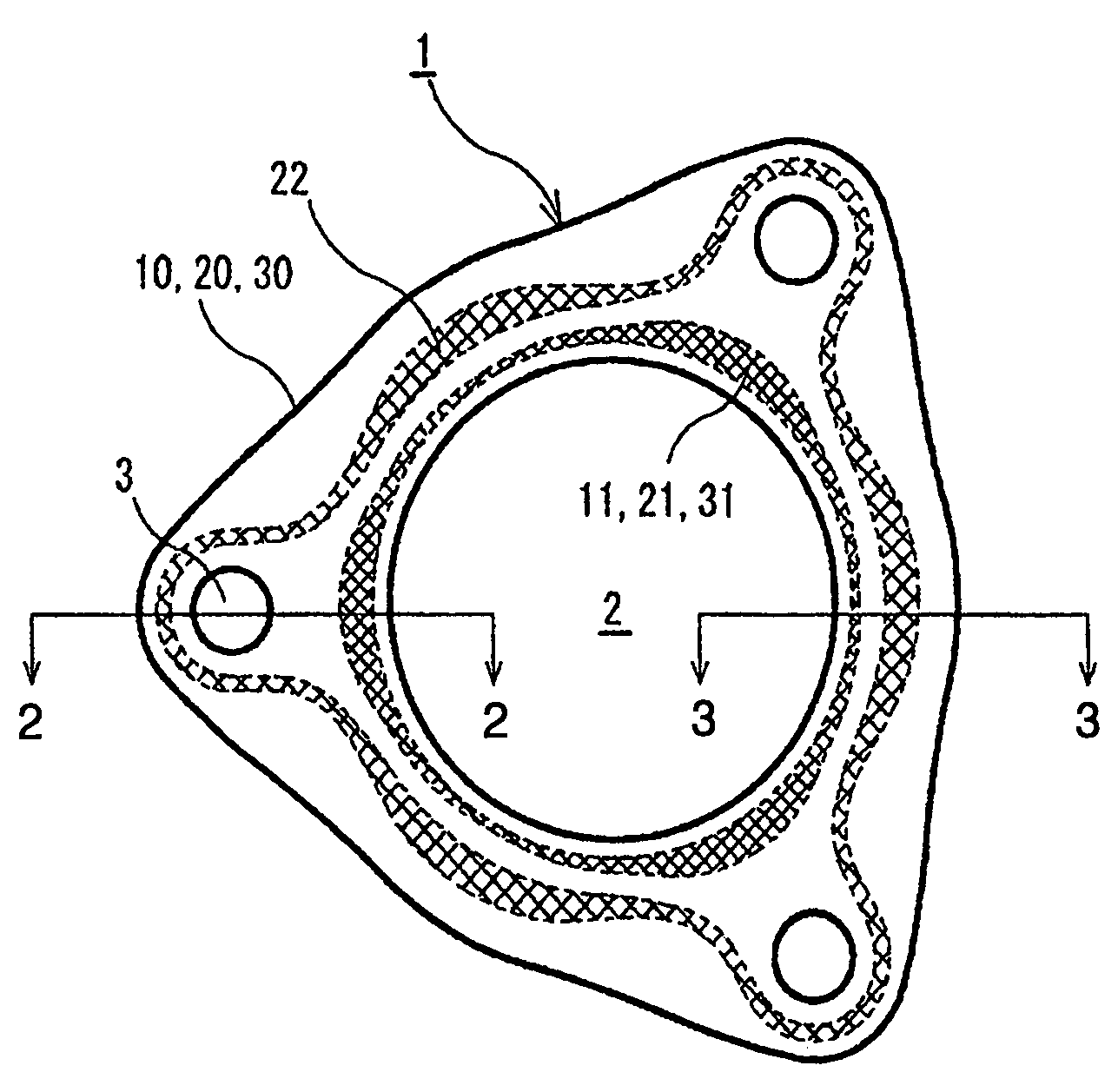
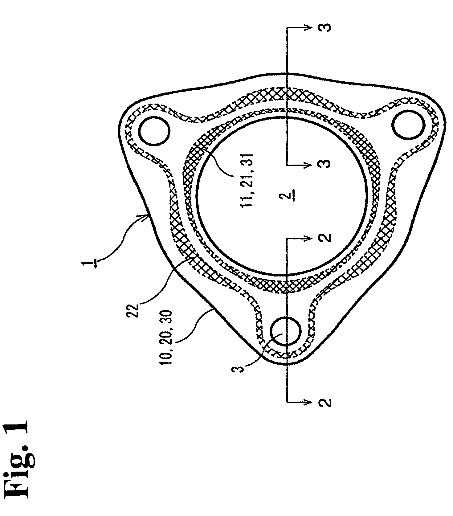
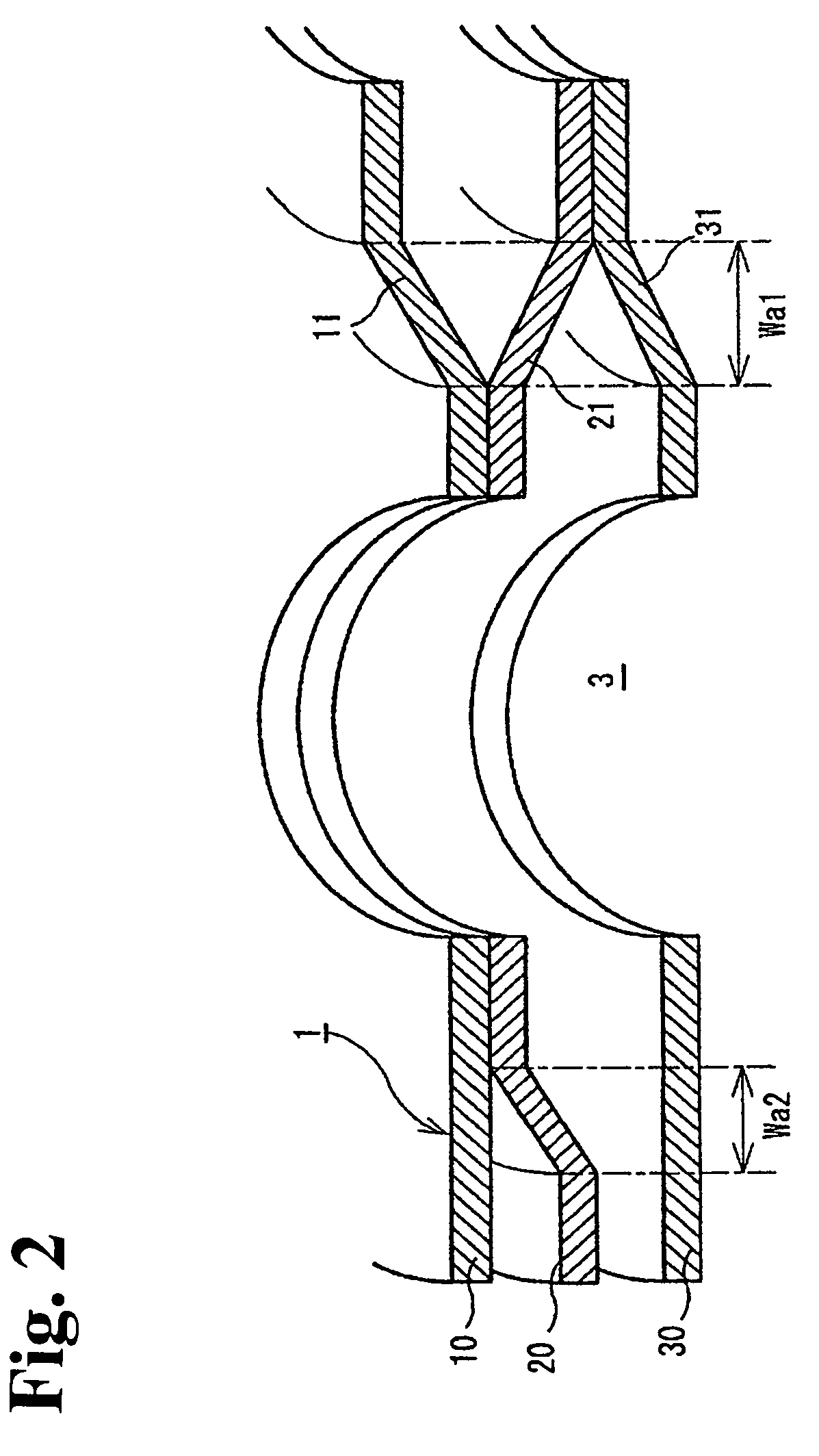
[0032]In the metal gasket 1 of the first embodiment shown in FIGS. 1 to 3, in addition to the above-mentioned two sheets of the first and second metal structural plates 10, 20, the third metal structural plate 30 is laminated. In the third metal structural plate 30, in a plan view, the inner-periphery side bead 31 is formed with the half bead with the slope such that an inner periphery side becomes abutted against the first metal structural plate 10 and that an outer periphery side thereof inclines toward the opposite side of the first metal structural plate 10. The inner-periphery side bead 31 overlaps with the inner-periphery side beads 11, 21 of the first and second metal structural plates 10, 20 in a plan view.

second embodiment

[0033]Also, in the metal gasket 1A of the second embodiment shown in FIGS. 5, 6, in addition to the above-mentioned two sheets of first and second metal structural plates 10, 20, fourth and fifth metal structural plates 10A, 20A, which have the same shape, are laminated in such a way as to be symmetric to the laminated surface. According to the structure, in a plan view, the inner-periphery side beads 11, 21, 21A, 11A overlap, and the outer-periphery side beads 22, 22A overlap.

[0034]According to the metal gasket 1 (or 1A), in the inner-periphery side beads 11, 21, 31 (or 11, 21, 21A, 11A) forming a primary seal, the neighboring portion of the bolt hole 3, wherein the impact of the bolt fastening force is strong and the sealing surface pressure is apt to be large, receives compressibility and a low surface pressure by reducing the compression resistance. Also, the portion between the bolt holes 3, wherein the impact of the bolt fastening force is weak and the sealing surface pressure...


PUM


Abstract

A metal gasket includes at least one structural plate having a sealing bore and bolt holes located around the seal bore. An inner bead is formed on the at least one structural plate to surround the sealing bore. The inner bead has first neighboring portions near the bolt holes and first outer portions outside the first neighboring portions. The first neighboring portion has a compression resistance smaller than that of the first outer portion. An outer bead is formed on the at least one structural plate to surround the inner bead such that the bolt holes are located inside thereof. The outer bead has second neighboring portions near the bolt holes and second outer portions outside the second neighboring portions. The second neighboring portion has a compression resistance greater than that of the second outer portion.

Description

BACKGROUND OF THE INVENTION AND RELATED ART STATEMENT[0001]The present invention relates to a metal gasket sandwiched between two members for sealing therebetween, and more specifically, a metal gasket being able to obtain an substantially equal sealing surface pressure all around a sealing bore while controlling a deformation of members sandwiching the metal gasket such as a deformation of a cylinder bore, flange or the like.[0002]Cylinder head gaskets or gaskets for intake and exhaust manifolds are used in a state of being sandwiched between a cylinder head and a cylinder block (cylinder body) of an automobile engine, or between the intake manifold and the intake pipe and between the exhaust manifold and the exhaust pipe; and are tightened by fastening bolts to seal fluid such as combustion gas, oil, coolant water and the like.[0003]Due to a recent lightweight and downsized engine, the engine has a low rigidity, and engine members have also low rigidities. As a result, a deformati...

Claims


Application Information

Patent Timeline
Patent Type & Authority Patents(United States)
IPC IPC(8): F02F11/00
CPCF16J15/0825F16J15/08
Inventor IMAI, TOSHIHIRO
Owner ISHIKAWA GASKET CO LTD
Learn More