Crawler track

Active Publication Date: 2010-11-09
JOSEPH VOEGELE AG
View PDF11 Cites 12 Cited by
  • Summary
  • Abstract
  • Description
  • Claims
  • Application Information

AI Technical Summary

Benefits of technology

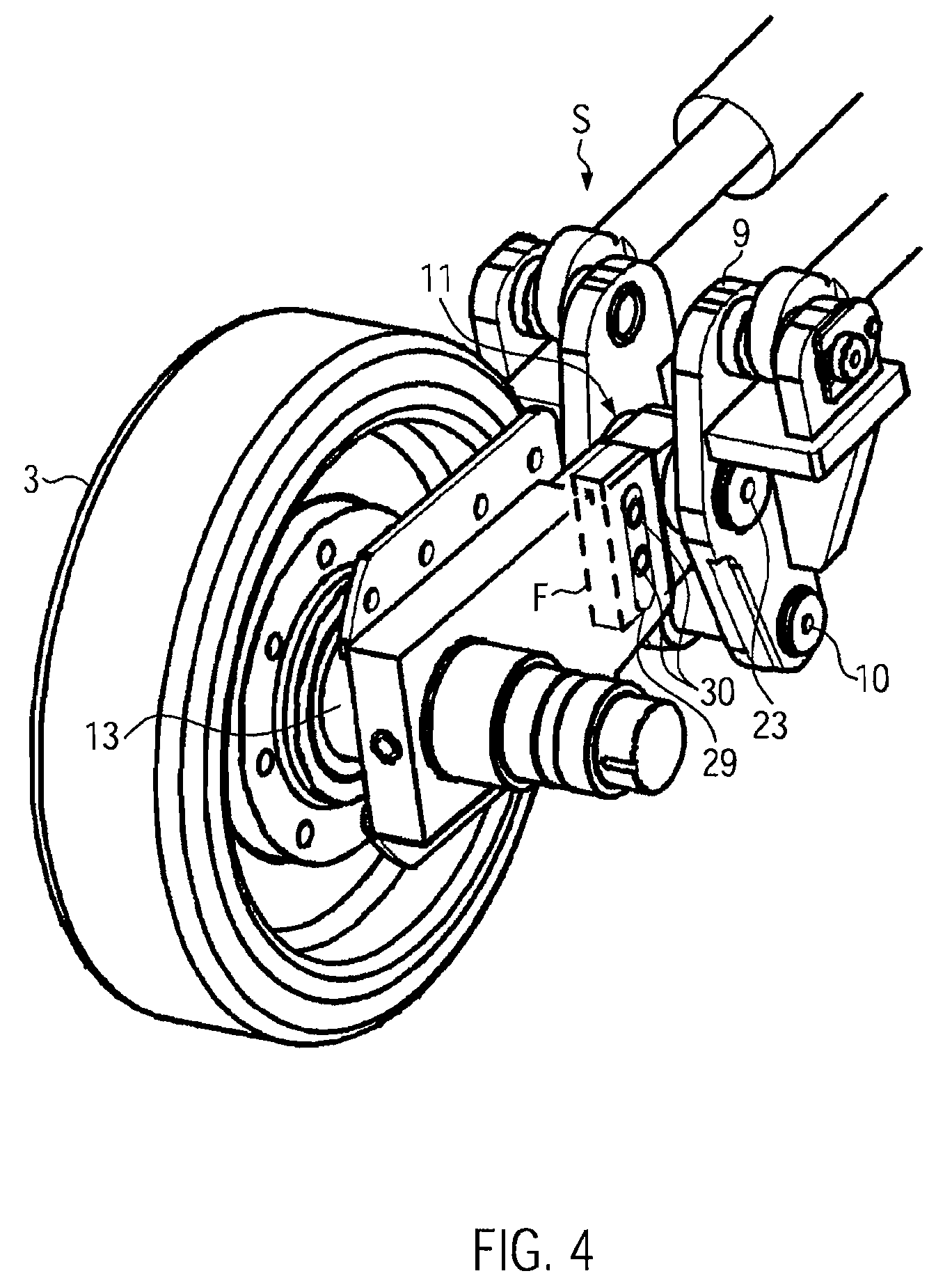
[0006]As the at least one guide wheel is supported in the guide part, which in turn is guided exclusively linearly in the track carrier, the tensioning lever does not need to stabilize the guide wheel. A stable lateral support of the guide wheel is assured whenever the guide wheel yields counter to or moves due to the tensioning force of the tensioning member. The tensioning member transmits the tensioning force via the tensioning lever to the guide part and in turn to the guide wheel. However, this force transmission takes place without undesirable lateral forces since the slide block only allows for the transmission of forces to the guide wheel, which forces are oriented in the linear direction of the movement of the guide part, and because the slide block compensates for the differences in the movements of the pivoting tensioning lever and the linearly moving guide part. A favourably long lever force arm can be used for the tensioning lever, because the tensioning force is transmitted from the tensioning lever via the slide block to the guide part. A structural separation is provided between the lateral support of the guide wheel and the transmission of the tensioning force. The tensioning device has a compact size, allowing to provide a small distance only between the guide wheel and the next caster wheel. Furthermore, a small diameter guide wheel (or a guide wheel pair) may be implemented, because the laterally stably supported guide part even transmits large lateral forces directly to the track carrier. The surface pressure at the slide block is moderate, such that even for long service times, only low wear has to be expected.
[0008]The slide block is arranged on a pivot axis defining in the slide block a first force transmission area of a determined size. At the location where the slide block is in contact either with the guide part or with the tensioning lever, in order to transmit the tensioning force and the support force, a second force transmission area is defined, which is larger in size than the first force transmission area, in order to minimize wear between flat surfaces sliding on each other and to reduce the surface pressure.
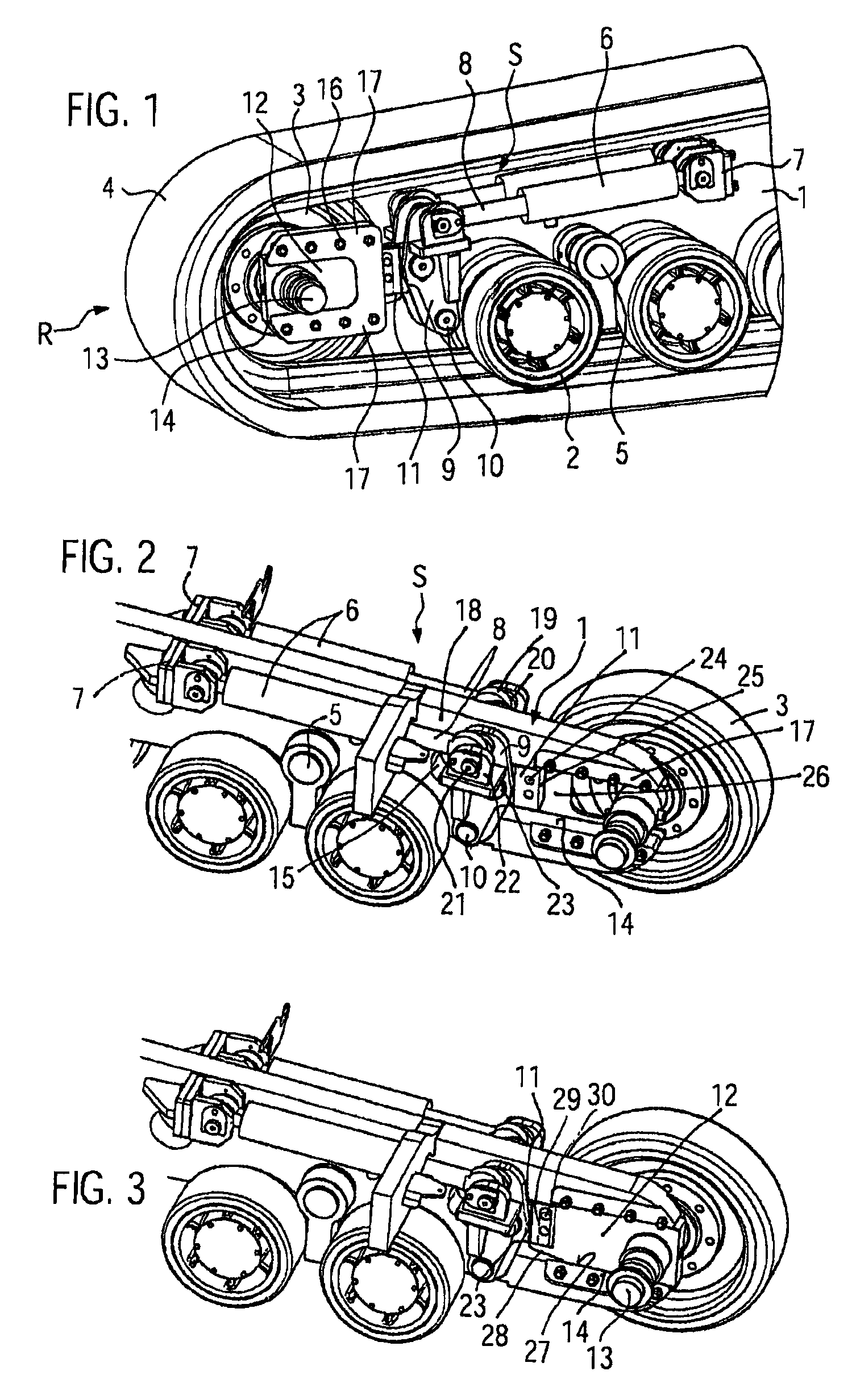
[0012]In an expedient embodiment, the slide block is engaging into the guide part, such that the contact area between the slide block and the guide part is shielded to the exterior against contamination (lubricant stored inside). The slide block may have sidewardly protruding pins, which engage into lateral slots in the guide part, which slots are open from the inside to the outside. The engaging guiding pins prevent irregular relative movements of the slide block in contact with the guide part. Furthermore, the engagement of the pins allows to pull back the guide part via the slide block.
[0015]When the pins engaging into the slot or the slots are offset in relation to each other, they will prevent the slide block inadvertently pivoting about the pivot axis when the tensioning device is in unloaded condition.
[0018]The tensioning member bearing may comprise two bearing blocks at the tensioning lever in order to transmit large forces to the tensioning lever without wear and without lateral components. Both bearing blocks may be penetrated by a common linking pin. A lug of a piston rod e.g. may be linked to the linking pin. Expediently, a universal joint is provided between the lug of the piston rod and the linking pin, in order to prevent generating lateral force components between a piston rod of the tensioning member and the tensioning lever.
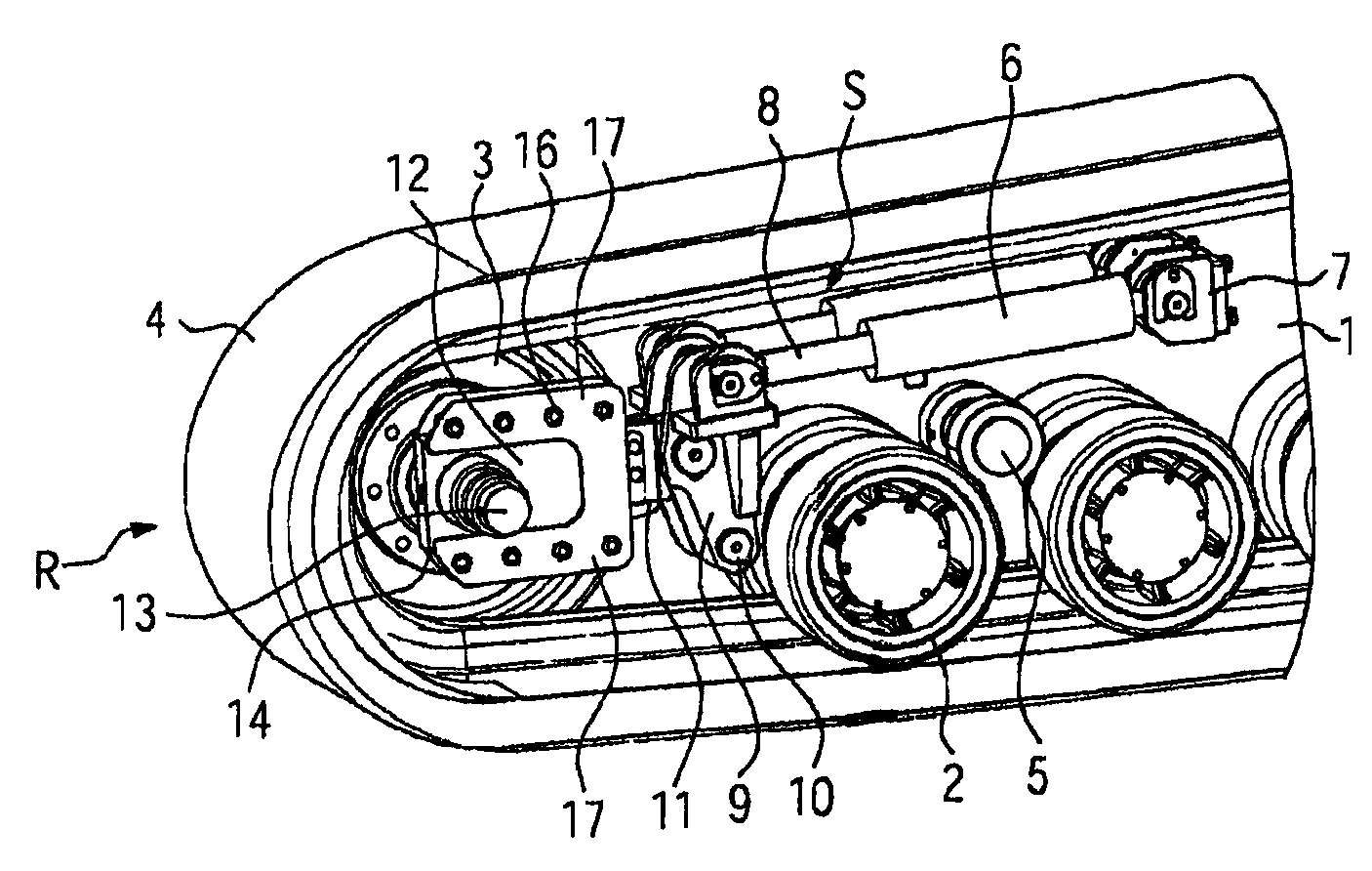
[0019]It may be expedient to match the positions of the pivot axis at the tensioning lever, of the track carrier pivot bearing and of the tensioning member at the track carrier with the positions of the guide part and the load bearing surface of the guide part, such that the direction of the tensioning force transmitted by the pivot axis is, at least substantially, parallel to the linear direction of the movement of the guide part. This concept avoids undesirable force components from the pivot movement of the tensioning lever, which force components would be inclined with respect to the guide part moving direction in the linear guiding jaw. Hence, the guide part can be moved smoothly and such that it underlies hardly any wear.

Problems solved by technology

However, this force transmission takes place without undesirable lateral forces since the slide block only allows for the transmission of forces to the guide wheel, which forces are oriented in the linear direction of the movement of the guide part, and because the slide block compensates for the differences in the movements of the pivoting tensioning lever and the linearly moving guide part.

Method used


Image

  • Crawler track
  • Crawler track
  • Crawler track

Examples


Embodiment Construction

[0025]A crawler track R, in FIG. 1, e.g. a rubber crawler track for a road finisher or a road finisher feeder vehicle, has, at the front side of a track carrier 1, one broad or two narrower guide wheels 3, with a respective solid rubber jacket, and respective, pair-wise caster wheels 2, on rocker bearings 5. (One guide wheel 3 of a pair, has been removed, for a better understanding). The caster wheels 2, on both sides of the track carrier 1, and the guide wheels 3, are surrounded by a rubber track 4 which also extends over a not shown driving wheel. At least one side of the track carrier 1 a tensioning member 6, e.g. a hydraulic tensioning cylinder, is mounted in a tensioning cylinder bearing 7. The tensioning member 6 instead may be a mechanical tensioning unit or a pressure spring. According to FIGS. 2 and 3, tensioning cylinders of equal dimensions, are mounted on both sides of the track carrier 1. The tensioning cylinder has a piston rod 8, which is linked to a tensioning lever ...


PUM


Abstract

In a crawler track comprising at least one guide wheel and caster wheels at a track carrier, at least one driving wheel for the track, and a guide wheel tensioning device including at least one tensioning member which acts on the guide wheel via a tensioning lever supported at the track carrier, the guide wheel is provided in a guide part which is exclusively linearly moveable and is laterally supported in the track carrier with a slide block arranged between the guide part and the tensioning lever, which slide block can slide crosswise and relatively to the linear direction of movement of the guide part while transmitting the tensioning force substantially parallel to the linear direction of movement of the guide part.

Description

[0001]The invention relates to a crawler track comprising at least one guide wheel and caster wheels at a track carrier, at least one driving wheel for the track, and a guide wheel tensioning device, including at least one tensioning member which acts on the guide wheel via a tensioning lever supported at the track carrier.BACKGROUND OF INVENTION[0002]In crawler tracks known from WO 81 / 01395 A, U.S. Pat. No. 5,927,412 A, U.S. Pat. No. 6,267,459 B1, DE 4193446 A, EP 0 721 879 A, U.S. Pat. No. 4,410,219 A, the guide wheel is pivoted about the pivot bearing of the tensioning lever at the crawler carrier when tensioning the track or CATERPILLAR chain. The tensioning lever has to transmit the tensioning force and at the same time to laterally support the guide wheel. As the pivot axis of the tensioning lever at the track carrier has a distance from the axis of the guide wheel, a stable lateral support of the guide wheel can hardly be achieved. Due to the arc-shaped path of the axis of th...

Claims


Application Information

Patent Timeline
Patent Type & Authority Patents(United States)
IPC IPC(8): B62D55/30B62D55/08
CPCB62D55/14B62D55/305
Inventor WEISER, RALF
Owner JOSEPH VOEGELE AG
Why Eureka
Try Eureka