Additive manufacturing method and object manufactured thereby

a manufacturing method and additive technology, applied in the direction of additive manufacturing processes, manufacturing tools, hinges, etc., can solve the problems of reducing production capacity, requiring longer production time, and requiring limited size of additive manufacturing chambers, so as to reduce the manufacturing space required for additive manufacturing process, reduce the effect of manufacturing space and increasing production density

Active Publication Date: 2021-06-17
TECO IMAGE SYST
View PDF0 Cites 1 Cited by
  • Summary
  • Abstract
  • Description
  • Claims
  • Application Information

AI Technical Summary

Benefits of technology

The present patent describes an additive manufacturing method to reduce the space required for production and increase production density. The method uses a large-sized object that is designed to be folded for production and can be easily unfolded after production through a rotation shaft. The unfolded object remains in place through an irreversible engaging structure, eliminating any possibility of sticking between components during the cooling process. The method simplifies the assembly process, saves manufacturing costs, and improves operational performance.

Problems solved by technology

However, the additive manufacturing technology must be implemented in a chamber with a limited size.
Moreover, when a large-size component or assembly is manufactured through a one-time manufacturing process in a larger-sized molding chamber, a longer production time is required.
It causes a reduction in production capacity.
However, the additive manufacturing technology still has a limitation of minimum distance.
Therefore, in a limited manufacturing space, the additive manufacturing technology still has many restrictions when it is applied to the batch production of various components.
The production efficiency cannot be improved effectively.

Method used


Image

  • Additive manufacturing method and object manufactured thereby
  • Additive manufacturing method and object manufactured thereby
  • Additive manufacturing method and object manufactured thereby

Examples


Embodiment Construction

[0040]The present disclosure will now be described more specifically with reference to the following embodiments. It is to be noted that the following descriptions of preferred embodiments of this disclosure are presented herein for purpose of illustration and description only. It is not intended to be exhaustive or to be limited to the precise form disclosed.

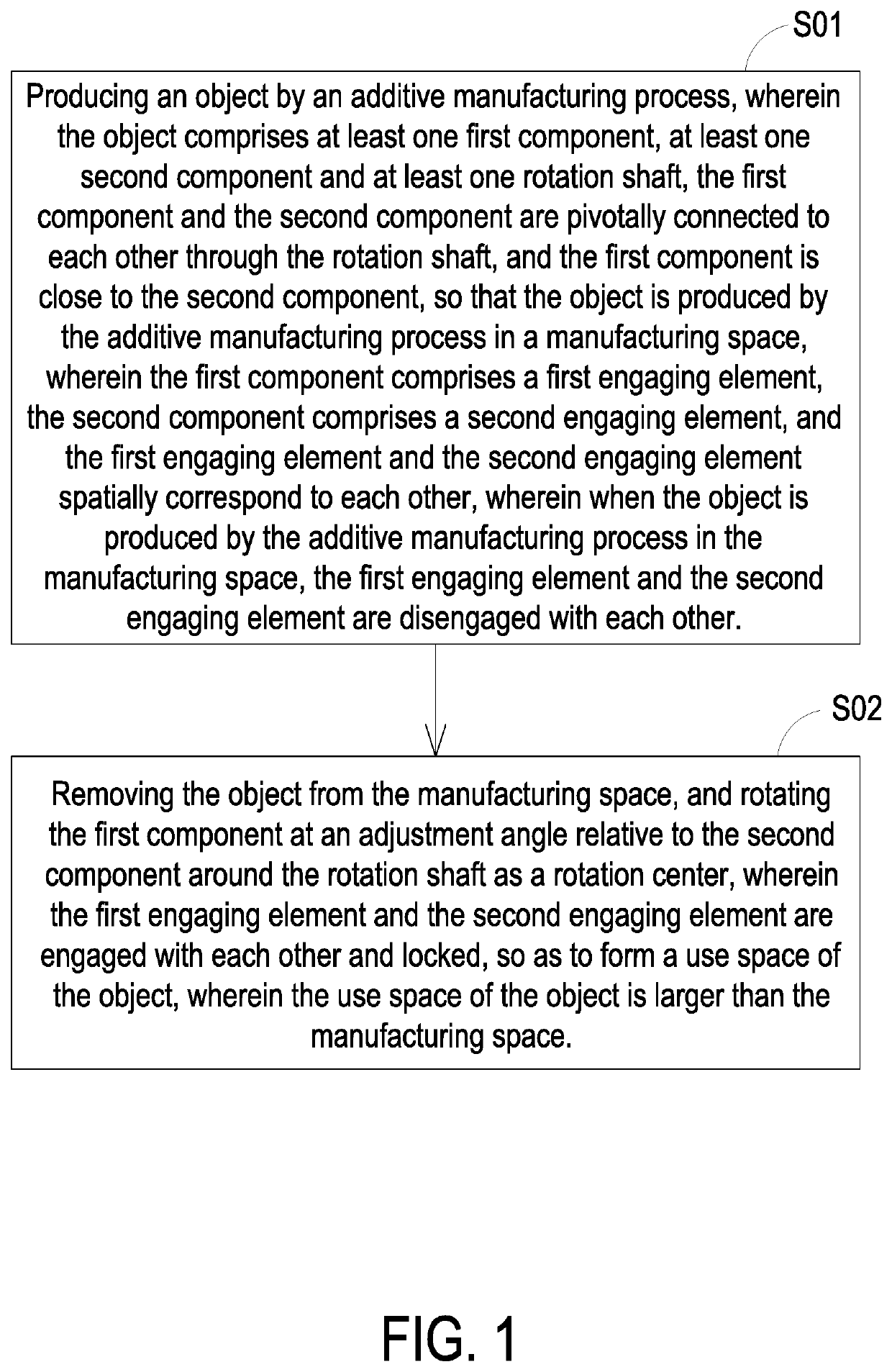
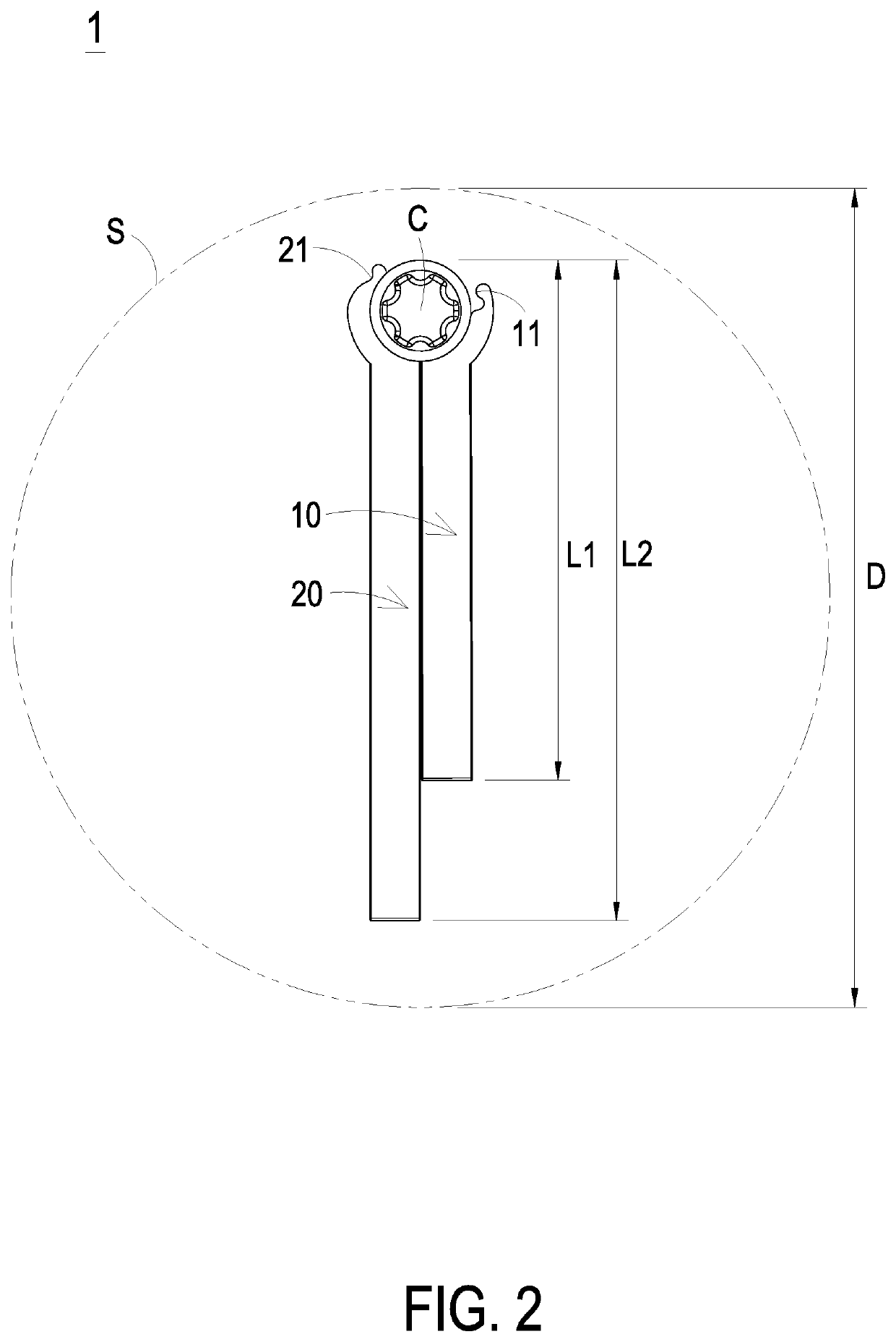
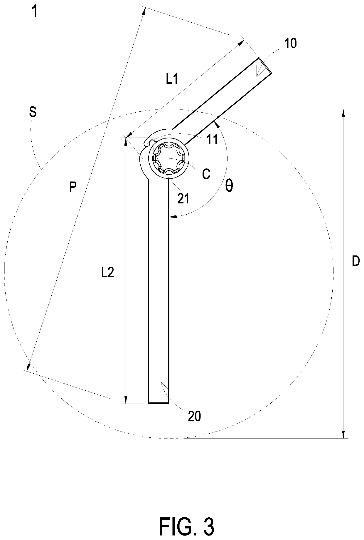
[0041]FIG. 1 is a flowchart illustrating an additive manufacturing method for reducing a manufacturing space required according to the embodiment of the present disclosure. FIG. 2 is a schematic diagram illustrating an object manufactured by the additive manufacturing process in a manufacturing space according to a first embodiment of the present disclosure. FIG. 3 is a schematic diagram illustrating the object unfolded to form a use space according to the first embodiment of the present disclosure. Firstly, as shown at the step S01, an additive manufacturing process is implemented to produce an object 1. In the embodiment, the...


PUM

PropertyMeasurementUnit
adjustment angleaaaaaaaaaa
separation distanceaaaaaaaaaa
adjustment angleaaaaaaaaaa

Abstract

An additive manufacturing method and an object manufactured thereby are disclosed. The object includes a first component and a second component pivotally connected to each other through a rotation shaft. A first engaging element of the first component and a second engaging element of the second component spatially correspond to each other. When the object is manufactured in a manufacturing space, the first component is close to the second component, and the first engaging element and the second engaging element are disengaged with each other. After the object is manufactured, the first component is rotated relative to the second component at an adjustment angle around the rotation shaft. The first engaging element and the second engaging element are engaged with each other and locked, to form a use space of the object larger than the manufacturing space. It is beneficial to achieve the purpose of reducing the required manufacturing space.

Description

FIELD OF THE INVENTION[0001]The present disclosure relates to an additive manufacturing method, and more particularly to an additive manufacturing method for reducing a manufacturing space required therein and an object manufactured thereby.BACKGROUND OF THE INVENTION[0002]With the development of additive manufacturing technology in recent years, the printing speed has also been greatly improved, so that the additive manufacturing has been utilized in mass production. Comparing to the conventional manufacturing, the restrictions of the additive manufacturing is fewer. While designing a product, the additive manufacturing can be utilized to improve the performance of the product. However, the additive manufacturing technology must be implemented in a chamber with a limited size. If the size of component or assembly is larger than the limited volume of the chamber, the component or assembly must be divided to reduce the size for manufacturing. After the respective manufacturing proced...

Claims


Application Information

Patent Timeline
Patent Type & Authority Applications(United States)
IPC IPC(8): B29C64/379B29C64/241B29C64/176B29C64/188
CPCB29C64/379B29C64/188B29C64/176B29C64/241B33Y80/00B33Y40/00B29C64/171B33Y10/00Y02P10/25E05D11/1007B22F10/00B22F5/10E05D11/1014B29C64/153
Inventor CHUNG, MING-CHIEHCHEN, TING-CHUN
Owner TECO IMAGE SYST
Why Eureka
Try Eureka