Vehicle brake system and method for increasing brake pressure in a first wheel brake cylinder and limiting brake pressure in a second wheel brake cylinder of a vehicle brake system

a brake system and vehicle technology, applied in the field of vehicle brake systems, can solve the problems of unsatisfactory flow of brake fluid into the second wheel brake cylinder b>14/b>, and achieve the effect of preventing an undesired increase of a second brake pressure, no overheating, and being versatile in its possible uses

Pending Publication Date: 2021-06-03
ROBERT BOSCH GMBH
View PDF0 Cites 0 Cited by
  • Summary
  • Abstract
  • Description
  • Claims
  • Application Information

AI Technical Summary

Benefits of technology

[0009]The present invention can be used to increase a first brake pressure in a first wheel brake cylinder of a brake circuit of a vehicle brake system, and at the same time to prevent an undesired increase of a second brake pressure in a second wheel brake cylinder of the same brake circuit (realized having the respective first wheel brake cylinder). Thus, the present invention provides possibilities for bringing about a brake pressure increase in at most one (first) wheel brake cylinder per brake circuit of a vehicle brake system, with simultaneous prevention of a brake pressure increase in at least one further (second) wheel brake cylinder of the vehicle brake system. Likewise, the present invention can be used to increase a first brake pressure in at least one first wheel brake cylinder of a first brake circuit of a vehicle brake system, and at the same time to prevent an undesired increase of a second brake pressure in at least one second wheel brake cylinder of a second brake circuit of the vehicle brake system. The present invention is thus versatile in its possible uses.
[0010]In an advantageous specific embodiment of the vehicle brake system in accordance with the present invention, the control device is designed to hold, during operation of the at least one brake pressure buildup device, a current strength maximum and a duty cycle of the pulse width-modulated signal low enough that the current strength maximum and the duty cycle are just sufficient for the second wheel outlet valve, controlled by the pulse width-modulated signal, to be permanently in its open state. A current strength, averaged over time, of the pulse width-modulated signal outputted to the second wheel outlet valve during the transferring of brake fluid into the first wheel brake cylinder is thus comparatively low, so that no overheating of the second wheel outlet valve (or of its electronics) need be feared.
[0011]For example, the control device can be designed to hold, during the operation of the at least one brake pressure buildup device, the current strength maximum and the duty cycle of the pulse width-modulated signal low enough that the pulse width-modulated signal has a current strength, averaged over time, of less than 0.5 A. Using the example procedure according to the present invention described here, a thermal load of the second wheel outlet valve (or its electronics) can thus reliably be minimized. Moreover, current consumption can be reduced using the procedure described here.
[0012]Preferably, the control device includes at least one flyback diode and is designed to output the pulse width-modulated signal to the second wheel outlet valve using the flyback diode. Thus, the flyback diode, frequently already in use, can also be used for the realization of the present invention. The present invention thus also contributes to increasing the multifunctionality of the flyback diode additionally used in this way.
[0013]For example, the vehicle brake system can include a master brake cylinder to which a brake actuating element is connectable or is connected and / or before which there is connected a brake booster, at least one pump, and / or at least one motorized plunger device as the at least one brake pressure buildup device. Thus, brake pressure buildup devices that are frequently already present in a vehicle brake system can additionally be used for the present invention. However, it is to be noted that the practicability of the present invention is not limited to the use of the examples listed here of the at least one brake pressure buildup device.
[0014]As mentioned above, the first wheel brake cylinder with its first wheel inlet valve and its first wheel outlet valve, and the second wheel brake cylinder with its second wheel inlet valve and its second wheel outlet valve, can be situated in a common brake circuit of the vehicle brake system. The present invention can thus be used to trigger different braking actions of two wheel brake cylinders of the same brake circuit.

Problems solved by technology

However, an undesired flow 50 of brake fluid into second wheel brake cylinder 14 often cannot be completely suppressed / prevented by closed second wheel inlet valve 20.

Method used


Image

  • Vehicle brake system and method for increasing brake pressure in a first wheel brake cylinder and limiting brake pressure in a second wheel brake cylinder of a vehicle brake system
  • Vehicle brake system and method for increasing brake pressure in a first wheel brake cylinder and limiting brake pressure in a second wheel brake cylinder of a vehicle brake system
  • Vehicle brake system and method for increasing brake pressure in a first wheel brake cylinder and limiting brake pressure in a second wheel brake cylinder of a vehicle brake system

Examples


Embodiment Construction

[0021]FIGS. 2a through 2d show a schematic partial representation of a vehicle brake system and coordinate systems for the explanation of a first specific embodiment of the method for increasing brake pressure in a first wheel brake cylinder and for limiting brake pressure in a second wheel brake cylinder of the vehicle brake system.

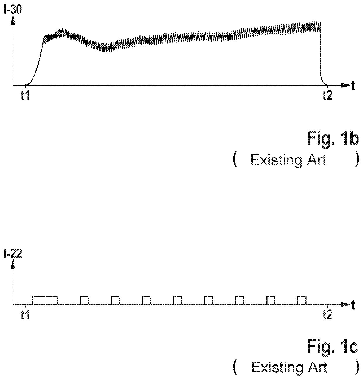
[0022]The vehicle brake system partly shown schematically in FIG. 2a has at least one brake circuit 10 having a first wheel brake cylinder 12, a second wheel brake cylinder 14, a first wheel inlet valve 16 assigned to first wheel brake cylinder 12, a first wheel outlet valve 18 assigned to first wheel brake cylinder 12, a second wheel inlet valve 20 assigned to second wheel brake cylinder 14, and a second wheel outlet valve 22 assigned to second wheel brake cylinder 14. Merely as an optional development, brake circuit 10 additionally includes a high-pressure switching valve 14, a changeover valve 26, a storage chamber 28 (such as a low-pressure storage c...


PUM


Abstract

A vehicle brake system and method for increasing the brake pressure in a first wheel brake cylinder and for limiting the brake pressure in a second wheel brake cylinder of a vehicle brake system. The method includes increasing a first brake pressure in the first wheel brake cylinder by controlling/holding a wheel inlet valve in its open state and controlling/holding a first wheel outlet valve in its closed state, and limiting an increase of a second brake pressure in the second wheel brake cylinder during the transfer of brake fluid into the first wheel brake cylinder by controlling/holding a second wheel inlet valve in its closed state and controlling a second wheel outlet valve into its open state. The second wheel outlet valve is controlled with a pulse width-modulated signal so that during the transfer of brake fluid, the second wheel outlet valve is permanently in its open state.

Description

FIELD[0001]The present invention relates to a vehicle brake system. The present invention also relates to a method for increasing brake pressure in a first wheel brake cylinder and for limiting brake pressure in a second wheel brake cylinder of a vehicle brake system.BACKGROUND INFORMATION[0002]FIGS. 1a through 1c show a schematic partial representation of a vehicle brake system and coordinate systems for the explanation of a conventional procedure for increasing brake pressure with simultaneous brake pressure limiting.[0003]FIG. 1a shows a schematic partial representation of a conventional brake system as described, for example, in German Patent Application No. DE 10 2012 222 974 A1. The conventional brake system has at least one brake circuit 10 having a first wheel brake cylinder 12, a second wheel brake cylinder 14, a first wheel inlet valve 16 assigned to first wheel brake cylinder 12, a first wheel outlet valve 18 assigned to first wheel brake cylinder 12, a second wheel inlet...

Claims


Application Information

Patent Timeline
Patent Type & Authority Applications(United States)
IPC IPC(8): B60T8/40B60T8/44B60T8/48
CPCB60T8/4072B60T8/442B60T2270/604B60T2220/04B60T8/4872B60T8/36B60T8/4081
Inventor MIYAGAWA, SHUICHIBODMANN, JOCHENNAGAKURA, YASUTAKA
Owner ROBERT BOSCH GMBH
Why Eureka
Try Eureka