Micro-bubble generator
a micro-bubble generator and generator technology, which is applied in mechanical equipment, transportation and packaging, sustainable biological treatment, etc., can solve the problems of inability to meet the requirements of existing aerators, the gas content of the liquid-gas mixing liquid generated by the existing bubble mixing device is too low to generate water-gas mixing liquid containing a large amount of dense bubbles in milky-white color, etc., to achieve the effect of improving the effect of washing, sterilization and pesticide degradation
- Summary
- Abstract
- Description
- Claims
- Application Information
AI Technical Summary
Benefits of technology
Problems solved by technology
Method used
Image

Examples
fourth embodiment
[0049]In a fourth embodiment, referring to FIGS. 10, 11A, 11B, 11C, 12A and 12B, the above-mentioned micro-bubble generator 100d is depressedly provided, on either the first junction surface 111 or the second junction surface 211, with a gasket groove 16. In the gasket groove 16, a gasket 17 slightly projecting outside of the gasket groove 16 is provided. Moreover, the drop between the gasket 17 and the gasket groove 16 is provided to remain the gas inlet gap 30 to the smallest extent between the first junction surface 111 and the second junction surface 211. In this embodiment, the gasket 17 is set as 1 mm in height. Specifically, the gasket 17 may be made of waterproof material with sufficient hardness, such as stainless steel and so on. Additionally, the gasket groove 16 is milled by a computer numerical control (CNC) machine tool to be a groove of 0.99 mm in height. Subsequently, the gasket 17 is placed, and the gas inlet gap 30 of 0.01 mm height is then formed, so as to reduce ...
fifth embodiment
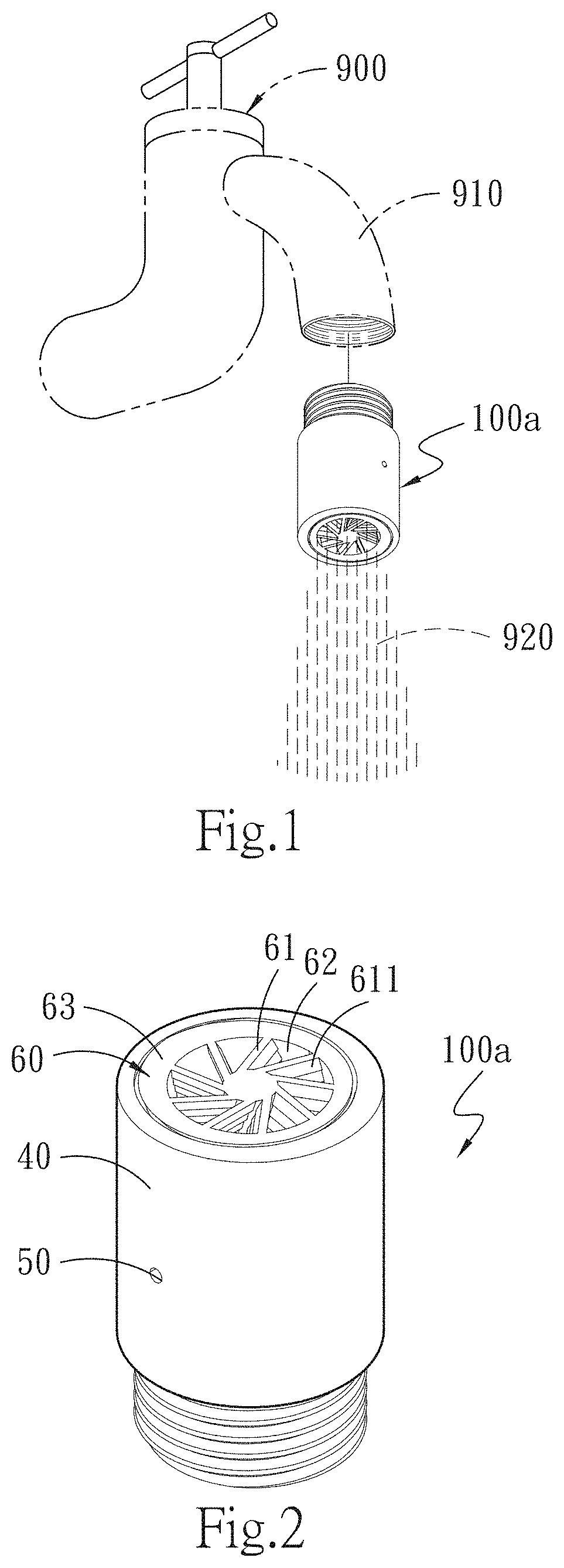
[0053]Referring to FIGS. 13 and 14, there is shown the present invention. In this case, the water inlet member 10e of the micro-bubble generator 100e is provided at the bottom thereof with an adapting screwed groove 18 in the form of threads. The adapting screwed groove 18 may be connected to a water pipe having a joint, while the water outlet member 20e is connected to the water outlet device 900, such as shower head and so on, in such a way that a large amount of bubbles are generated when water is discharged, so as to enhance the effect of washing. In this embodiment, the water inlet member 10e is projectingly provided on the first junction surface 111 with an embossing gasket 19, the embossing gasket 19 being used for maintaining the gas inlet gap 30 between the water inlet member 10e and the water outlet member 20e when the two members are abutted against each other.
sixth embodiment
[0054]Referring to FIGS. 15A and 15B, there is shown the present invention. A micro-bubble generator A0 includes an accommodating part A1 and a bubble-multiplying part 26. The accommodating part A1 includes a first accommodating trough A11 adjacent to the input end 910, a plurality of accommodating channels A12 communicated with the first accommodating trough A11, and a second accommodating trough A13 adjacent to the output end 920 and communicated with each accommodating channel A12. The bubble-multiplying part 26 includes the plurality of spacing rings 262 concentrically provided within the second accommodating trough A13, and the plurality of multiplying nets 261 provided between the spacing rings 262, respectively. In this embodiment, each spacing ring 262 is preferably 0.2 to 1 mm in height, while the mesh size of each multiplying net 261 is in the range of 0.048 to 0.3 mm. The micro-bubble generator A0 may be suitable for the liquid containing air itself, such as tap water and...
PUM
 Abstract
Description
Claims
Application Information
 - R&D
- Intellectual Property
- Life Sciences
- Materials
- Tech Scout
- Unparalleled Data Quality
- Higher Quality Content
- 60% Fewer Hallucinations
Browse by: Latest US Patents, China's latest patents, Technical Efficacy Thesaurus, Application Domain, Technology Topic, Popular Technical Reports.
© 2025 PatSnap. All rights reserved.Legal|Privacy policy|Modern Slavery Act Transparency Statement|Sitemap|About US| Contact US: help@patsnap.com